RG-ES206GS-P Series Switches Hardware Installation and Reference Guide Product Overview
5
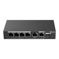
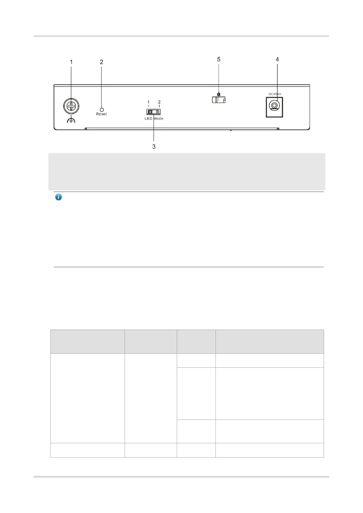
Figure 1-3 Back Panel of RG-ES206GS-P
1. Grounding stud
2. Reset button
3. LED mode switch
4. DC power input
5. Kensington lock
Note
● Reset button: Press for less than 2 seconds and release, the system restarts; press for more than 5
seconds until the system LE blinks, and then release, the system restores to factory settings and restarts.
● LED switch toggled to left (Mode 1): the port LED status indicates the status of traffic transmission. Solid
green means that the port is link up, while blinking green means that the port is transmitting and receiving
data.
● LED switch toggled to right (Mode 2): The port LED status indicates the PoE status. Solid green means
that the port is supplying power, while blinking green means that the port is in power overload state.
Cooling
RG-ES206GS-P adopts natural cooling. To ensure that the switch works properly in the specified environment,
a minimum clearance of 100 mm (3.94 in.) must be maintained around the device to ensure proper ventilation.
Dust the device every three months to avoid blocking the ventilation openings on the housing.
Figure 1-4 LED
System is not powered on.
If the power of PoE exceeds 54W, the
newly connected PD cannot be
powered up because of insufficient
power, but the switching function will
remain affected.
System is operating normally.
 Loading...