Hardware Installation and Reference Guide Product Overview
7
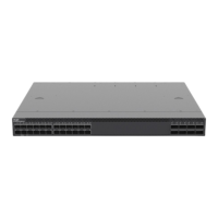
The RG-S6150-48VS8CQ-X switch supports debugging, configuration, maintenance, management and host
software uploading of Console ports.
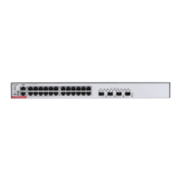
Console port: Use RS-232 interface electrical level and standard RJ45 connector. This interface is
connected with the serial port of terminal PC to perform system debugging, configuration, maintenance,
management, and host software uploading.
MGMT port: This is an out-band Ethernet port, which uses standard RJ45 connector. This interface is
connected with Ethernet port of a PC to perform program downloading. The user can manage and maintain
the switch remotely through this interface. Use a standard Ethernet cable to connect the MGMT port and
the Ethernet port of the PC.
SFP28 port: There are 48 10G SFP28 ports (A license is needed for a 25G SFP28 port.), which support
optical modules.
QSFP28 port: There are 8 100G QSFP28 ports, which support optical modules. These ports can also work
in 4 x 25G mode.
LED
Table 1-3 LED
The system is not powered up.
1. One of the modules of the system fails.
2. There are less than 3 fans.
3. The internal or partial temperature exceeds the
warning working temperature, and the switching
service resets.
The system is initializing.
The system is operational.
1. The temperature gets to the warning threshold.
2. Only 3 fans are in the position.
3. One of the dual powers is not connected with the
AC power cord.
Locator LED (Front
panel/Back panel)
Locator LED is controlled by CPLD. Locating function
is disabled.
Device locating is enabled and the technical support
engineers turn on or off the locator LED remotely.
The port is not connected.
The port is connected at 10/100/1000 Mbps.
 Loading...