M.HIST.0101.23 R2
Page 3 of 36
January, 26
th
2021
INDEX
1. APPLICATION ............................................................................................................. 4
2. INTRODUCTION ......................................................................................................... 4
2.1. General description ........................................................................................................ 4
2.2. MAIN FEATURES .......................................................................................................... 5
2.3. Electronic circuit features ............................................................................................... 5
2.4. Output power modules ................................................................................................... 5
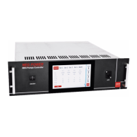
2.5. NEG POWER: the front panel of the unit ....................................................................... 6
2.6. NEG POWER: the rear panel of the unit ........................................................................ 6
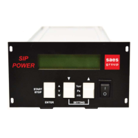
2.7. NEG POWER SMALL: the front panel of the unit ........................................................... 7
2.8. NEG POWER SMALL: the rear panel of the unit ........................................................... 7
2.9. NEG POWER Dimensions and Weight .......................................................................... 8
2.10. NEG POWER SMALL Dimensions and Weight ............................................................. 8
3. INSTALLATION ........................................................................................................... 9
3.1. Rack mounting ............................................................................................................... 9
3.2. Electrical connections ..................................................................................................... 9
3.3. Cleaning ....................................................................................................................... 10
4. MODE OF OPERATION ............................................................................................ 11
4.1. Power on ...................................................................................................................... 11
4.2. The General Menu ....................................................................................................... 11
4.3. The General Setup button ............................................................................................ 12
4.4. The Setup Menu ........................................................................................................... 15
4.5. The Limit Setup button ................................................................................................. 17
4.6. The SAVE and CANCEL buttons ................................................................................. 18
4.7. The START/STOP buttons ........................................................................................... 18
4.8. The recommended settings .......................................................................................... 19
4.9. Heating (Activation/Conditioning) without stop ............................................................. 20
4.10. Custom: a Generic Pump for Customer Settings ......................................................... 20
4.11. Alarms .......................................................................................................................... 21
4.12. Alarm history ................................................................................................................ 22
4.13. Information page .......................................................................................................... 22
5. THE OUTPUT CONNECTOR FUNCTION ................................................................ 23
5.1. Pin layout of IN/OUT Interface connector ..................................................................... 23
5.2. RS232 / RS485 Interface ............................................................................................ 23
6. Electrical Specifications ............................................................................................. 24
7. Summary Table of the NEG Pumps controlled by the NEG POWER ........................ 25
8. PRODUCT CONFIGURATIONS AND ACCESSORIES ............................................ 26
8.1. NEG POWER configurations and accessories: ............................................................ 26
8.2. Pump cables and accessories: ..................................................................................... 27
9. DECLARATION OF CE CONFORMITY .................................................................... 28
10. INSTRUCTION FOR INSTRUMENT DISPOSAL ...................................................... 29
11. WARRANTY CONDITIONS ...................................................................................... 30
12. SERVICE ................................................................................................................... 31
12.1. Sales & Service Locations: ........................................................................................... 31
APPENDIX A: Supply cables ............................................................................................. 32