M.HIST.0101.23 R2
Page 6 of 36
January, 26
th
2021
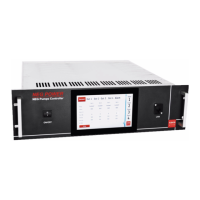
2.5. NEG POWER: the front panel of the unit
1. ON/OFF instrument power switch
2. touch screen display
3. LAN connector: RJ45 connector for Ethernet
4. handles for transport
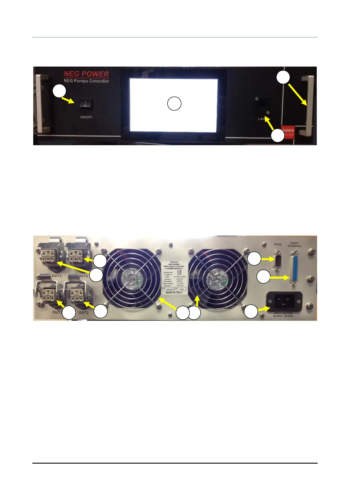
2.6. NEG POWER: the rear panel of the unit
5. instrument MAININPUT IEC 16 A: plug for mains power supply
6. IN/OUT interface connector with INTERLOCKS
7. RS485 serial interface
8. Fan for power modules 1 and 2
9. Fan for power modules 3 and 4
10. OUTPUT 1 pump connector
11. OUTPUT 2 pump connector
12. OUTPUT 3 pump connector
13. OUTPUT 4 pump connector
2
6
11
12
10
13
5
7
89
1
3
4