VHF 5000 System Functional unit workshop service
3-43
3.3.3 Mechanical assembly and disassembly
Removing/installing the spiral cable of the HS5001 Handset
Use the following procedures & illustrations to remove/install the spiral cable of the HS5001 handset. The
sequence of the procedures applicable to the removal and the installation respectively is consecutively
numbered 1 through 3 and should be carried out in accordance with this
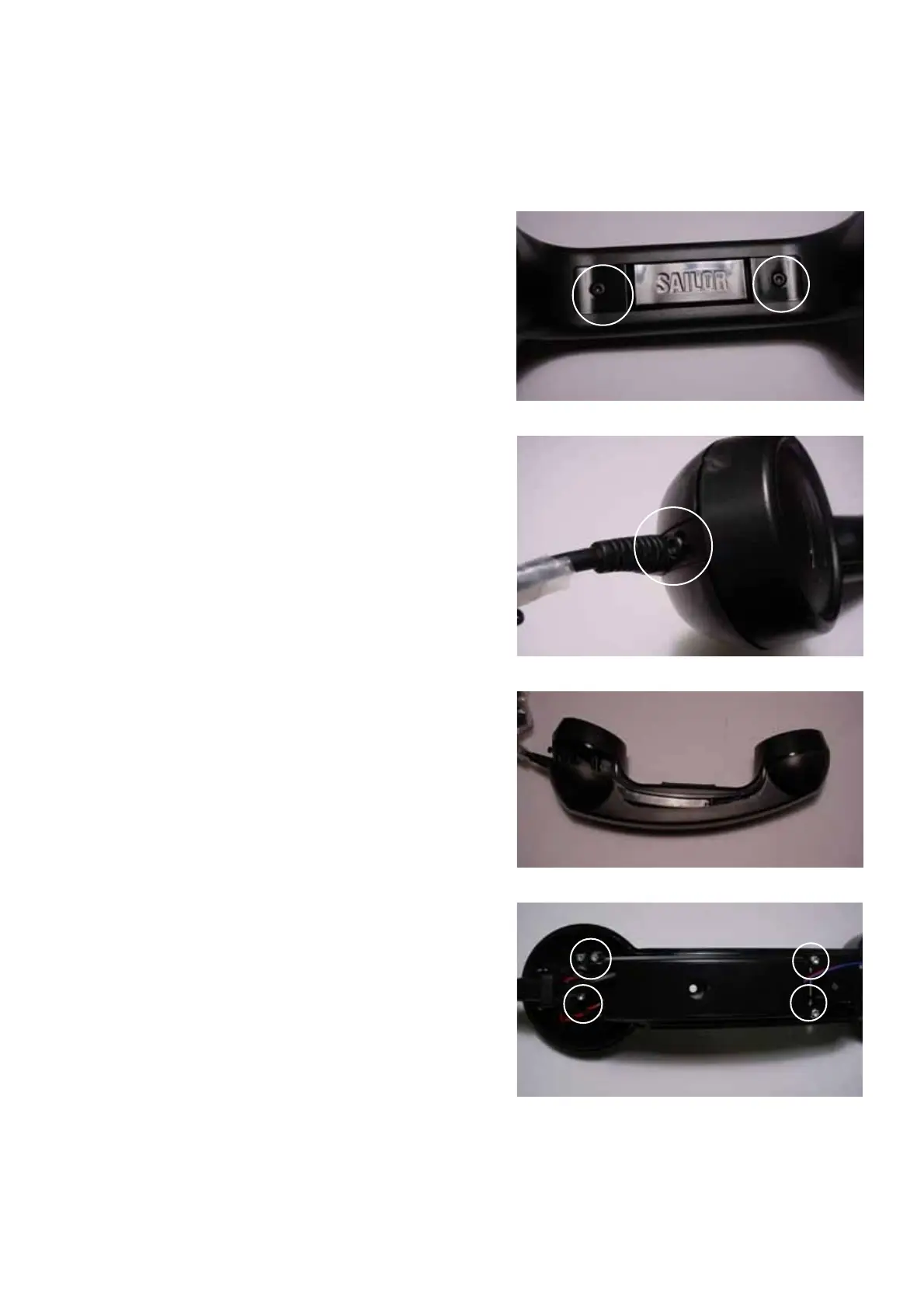
Fig. 2
Fig. 1
Fig. 3
Fig. 4
Removal:
• Remove the 2 x screws as indicated in Fig. 1.
Loosen (only) the screw at the cable end of the
handset app. two turns – refer to Fig. 2.
The upper handset part can now be separated from
the bottom part – refer to Fig. 3.
• Remove the 4 x screws (crosshead) securing pcb
tray to handset bottom part, refer to Fig. 4.
Lift spiral cable bushing from its supporting
bracket.
• Remove silicone packing from pc-board tray.
• Gently lift pc-board tray from handset bottom part
just enough to turn over the tray to gain access to
the pc-board.
Disconnect spiral cable connector from pc-board
(use a small flat head screwdriver to disengage
connector from socket.
Carefully guide connector out from tray through
cutout, being careful not to damage the reed switch
in the process, see Fig. 7.
Installing:
• Gently guide spiral cable connector through cutout
in pc-board tray, being careful not to damage the
reed switch in the process, see Fig. 7.
Connect spiral cable connector to pc-board socket
making sure connector is seated properly in socket.
• Install silicone packing over pc-board tray, making
sure that packing groove is seated correctly all the
way around.
• Position pc-board tray correctly in handset bottom
part.
Install 4 x screws securing tray and fasten by
applying a torque of max. 0,3 Nm.
Slide spiral cable bushing over its supporting
bracket.
Tools required:
Torx screwdriver, size 8 or Crosshead screwdriver,
size 2.5mm.
0608