VHF 5000 System Functional unit workshop service
3-9
3.2.10 Removing/installing the SMPS from the VHF transceiver unit.
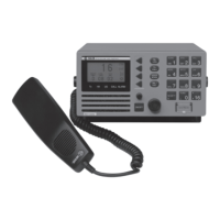
The switch mode power supply module is a candidate for replacement identified from a number of flows:
(Replace)
Replace
SMPS
(PC-Flow)
Power
connector
(SPP-Flow)
SPARC-II
power
(HSC-Flow)
Handset
connector
(MKDC-
flow)
MKD power
(MPC-Flow)
Module
power
40461
(Replace)
Replace
SMPS
(PC-Flow)
Power
connector
(SPP-Flow)
SPARC-II
power
(HSC-Flow)
Handset
connector
(MKDC-
flow)
MKD power
(MPC-Flow)
Module
power
Fig. 2 SMPS module replacement. (See section 3.2.15 for details on fault identification)
No other fault identification tests are available before replacement of this module.
Use the following procedures & illustrations to remove/install the SMPS. The sequence of the procedures
applicable to the removal and the installation respectively is consecutively numbered 1 through 5 and should
be carried out in accordance with this.
1007
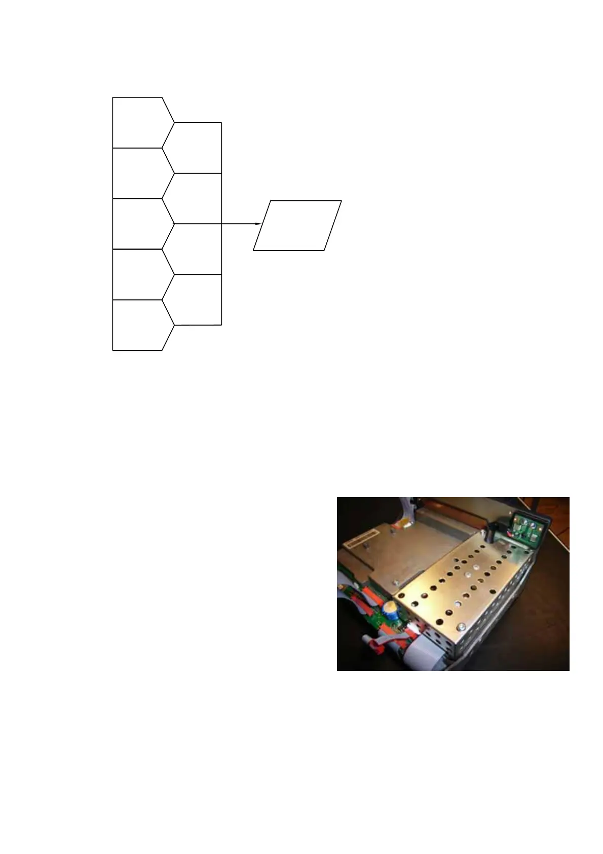
Removal:
• Gain access to the build-in power supply module by
removing the cover and the front part assy’ (Control
Unit) from the radio.
The PSU is located in right hand side of the radio
as viewed from front.
Fig. 1
 Loading...