VHF 5000 System Installation
5-11
5.2.5 Connecting the LB5007 LAN box
rect connection between the LB5007 and the printer server must be done using the crossed Ethernet cable.
Alternatively, if operating in an office environment, an Ethernet HUB can be used, in which case the HUB does
the terminal-terminal crossing inside.
Note: The LB5006 service tool is not qualified to operate directly on the internet, so do not plug it into an open
internet connection. The router to the internet would probably not allow this anyway.
The LB5007 can also be used as service tool box. In installations with an LB5007 the service PC can be
connected in place of the printer server during service. A selection of connection scenarios are outlined below:
5.2.6 Multiple unit equipment
If a vessel is equipped with multiple VHF radios the MMSI numbers will be the same for all radios. The Sailor
RT5000 series radios – in such a system - can be addressed individually by programming the 10
th
digit in the
MMSI number different from 0. Thus giving the possibility to differentiate between (up to) 10 transceivers.
It is important for the installer to know the feature is only active for individual routine calls. All other calls types
(especially Distress, urgency and safety calls) are not affected by this facility.
The installer must assure that the VHF unit placed on the main vessels steering position, has legally
programmed the default MMSI number (with the 10
th
digit set to zero). The operator shall be advised not to
change the configuration of the main communication unit, because this would violate regulations.
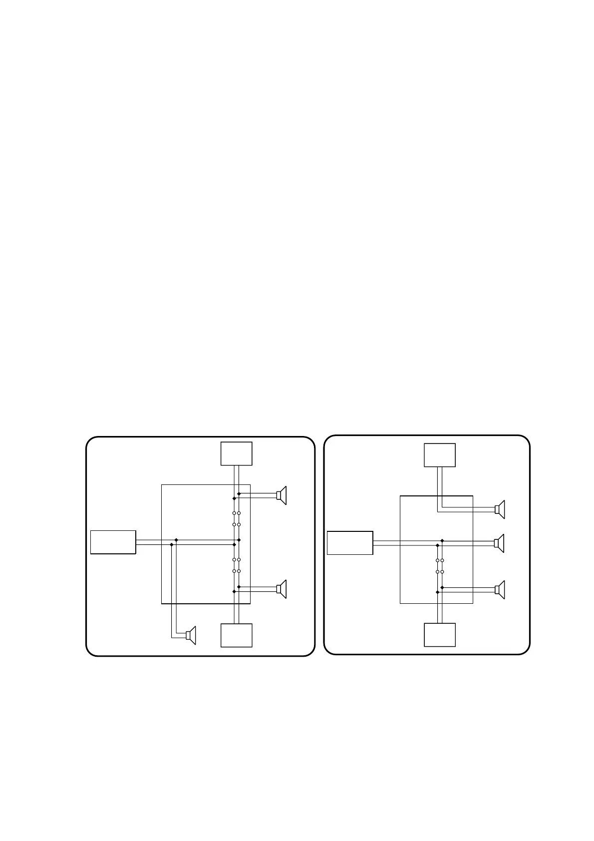
5.2.7 External speakers for the transceiver or remote CU positions
Opptional External speakers can be installed to follow volume control on either RT5022/RT5020, CU5000 or
both.
Because each unit (transceiver and CU) is having a built in amplifier the following must be considered: If CU5000
are included in the installation must either the EB5008 or the CB5009 be modified via jumpers.
CU5000/
EB5008
CU5000/
CB 5009 Connection Box
EXT/CU
LS
VHF RT502x/
EB5008/CB5009
X4 (11-12)
X8 (1-2)
X9 (1-2)
X5 (11-12)
X3 (11-12)
J3J4
REMEMBER
cut J1 & J2, if CU5000 is
connected to x4
40298
EB5008
J1
J2
EXT/CU
LS
EXT
LS
X6 (11-12)
Cut J3 & J4, if CU5000 is
connected to x5
CU5000/
EB5008/
CU5000/
EB5008 Extension Box
EXT/CU
LS
VHF RT502x/
EB5008/CB5009
X1 (11-12)
X4 (1-2)
X6 (1-2)
X3 (11-12)
X2 (11-12)
J1
J2
REMEMBER
cut J1 & J2, if CU5000 is
connected to x3
40297
CU
LS
X5 (1-2)
EXT
LS
CB 5009
0608
 Loading...