Functional unit workshop service VHF 5000 System
3-10
1007
• Release the sealing compound from the PSU
shielding cover by cutting, using a sharp knife.
Clean connector and PSU cover for any residual
sealing compound.
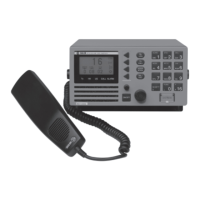
• Locate the 8-pin connector in front of the PSU
module.
This connector is secured to shielding cover of the
PSU module by means of a sealing compound.
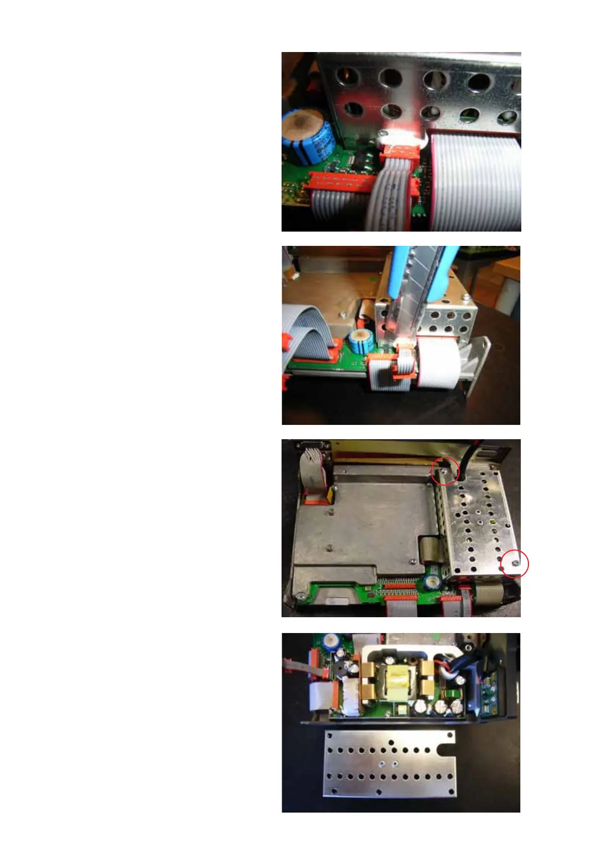
• Remove the cover of the PSU by removing two (2)
screws (Torx TX10) (see Fig. 4) securing the cover
to the PSU chassis and carefully lift the cover from
the PSU.
Retain screw and cover for re-installation later.
Remove the four (4) TORX TX10 screws located
inside the PSU at the base, the two (2) stand offs
and two (2) TORX TX10 screws located at the rear
side of the radio securing the E-shaped cooling
profile to the radio chassis.
Remove the two (2) 20-pin ribbon cable connectors
at the baseband PCB and RF PCB respectively. Do
NOT remove connectors at PSU side since the
ribbon cables will be included with the replacement
PSU module.
Fig. 2
Fig. 3
Fig. 4
Fig. 5
 Loading...