08 RT310i Installation Manual
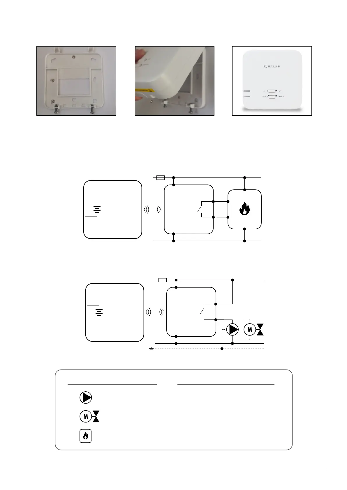
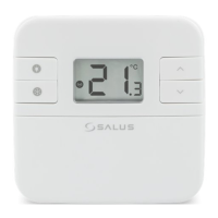
2.3.2.3 Receiver’s wall mounting
2.3.2.4 Connection description
Fit the front housing.
Press lightly
Fix the backplate to the wall Align the front housing
at the top edge.
or
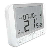
Legend:
Pump
Boiler
Actuator
Symbols explanation
L, N - 230V AC powe supply
COM, NO - voltage-free outputs
eg. boiler connection
Boiler (boiler connection*) - contacts
in the boiler for connecting an ON / OFF
thermostat (according to the boiler manual)
L
AC 230V
COM
NO
N
N
L
L
N
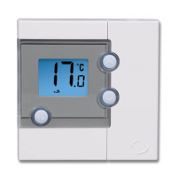
RXRT510
L
AC 230V
N
COM
NO
RXRT510
N
L
MAX
16 (5) A
091FLR
091FLR
Fv
Fv
2
2
3V
3V
2 x AA
2 x AA
16 (5) A
BOILER CONNECTION*
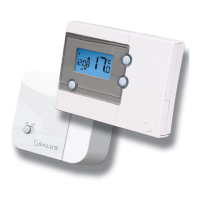
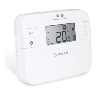
RT310i
RT310i