13ZetrOZ Systems Product Support 1-800-202-9831
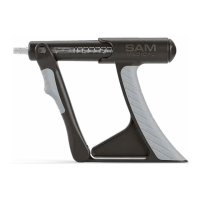
Remove the sam Device components (Figure
1) from the packaging and inspect for any damage
that may have occurred during shipment. Charge
the device for up to 6 hours or until the Power
Controller Indicator LED is Green. The sam Device
arrives only partially charged due to generally
accepted shipping practices.
9.1. CHARGING THE POWER
CONTROLLER
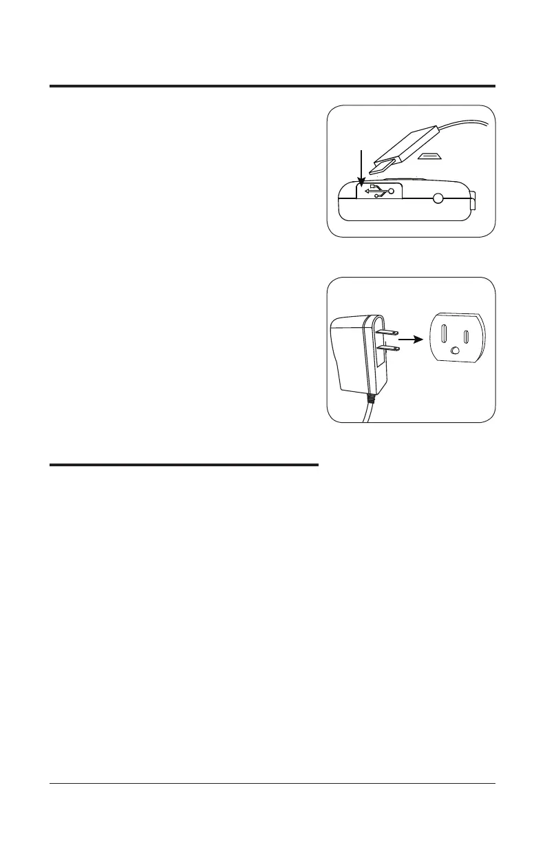
A. Peel back the dust cover on the bottom
of the sam Power Controller and plug
the micro USB end of the sam Electrical
Charger into the charging port.
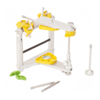
B. Plug the electrical charger into a 120230
VAC wall outlet. The sam Power Controller
indicator LED will be amber. When the
device is fully charged the top right indicator
LED will change from amber
to green.
10. Treatment Options
10.1. TREATMENT DURATION
The sam Ultrasonic Diathermy Device provides
ultrasound therapy at a preset frequency and
intensity. The user can program the treatment
duration to be 1, 2, 3, or 4 hours. The maximum
treatment duration setting on the sam Device
is 4 hours. Treatment duration should be set to
the minimum increment required for effective
therapy. Due to individual differences in skin type
and tolerance, it is recommended to begin with a
1 hour treatment. Increase treatment duration in
subsequent applications only as tolerated. Maximum
usage time is 4 hours per day per treatment area.
The sam Device may be used while charging.
Charging the device during treatment has no impact
on device frequency or intensity output settings. If
using sam while charging, position the device in
such a way that the charger cable is easily removed
from the power Controller if needed.
Bottom of sam Power Controller
Micro USB
Wall Charger
Outlet
Bottom of sam Power Controller
Micro USB
Wall Charger
Outlet
figure 3B
figure 3A
9. Initial Setup Instructions