+
-
+
-
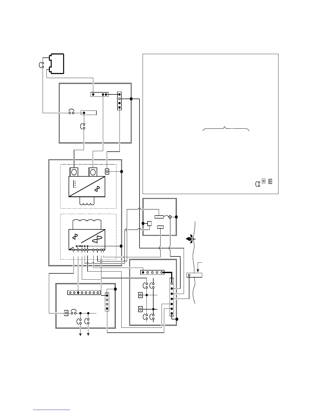
NOTES:
1: Please ensure that Neutral of the Generator is bonded to the frame / chassis internally.
If not, bond the Neutral terminal to the Earth Terminal “E” externally.
5
8
6
7
4
9
10
12
11
13
Grounding Electrode (GE)
i.e. the Ground Rod embedded
in earth.
ELECTRICAL
SUB-PANEL FOR
EVO (SINGLE
PHASE: 120 VAC)
GRID ELECTRICAL PANEL
(SPLIT PHASE: 120/240 VAC)
D.C. ELECTRICAL
PANEL
N-B
G-B
G1
G2
N-B
G-B
G-B
A B
A.C. Section D.C. Section
Neg. (-)
Bus
Lead Acid
Battery Bank
Pos. (+)
Bus
EVO INVERTER CHARGER
To loads
backed up
by EVO
B
L.
N.
G.
E.
N-G.
N-B.
G-B.
G1.
SBJ.
G2.
GE.
4.
5.
6.
7.
8.
9.
10.
11.
12.
13.
Line terminal of generator output
Neutral terminal of generator output
Ground terminal of generator output
Earth terminal of generator (Bonded to the frame / chasis of the generator)
Neutral to Ground Bond
Neutral Bus Bar
Grounding Bus Bar
AC Input and AC Output Grounding terminals in EVO
(Are internally bonded to the metal frame / chassis of the unit)
System Bonding Jumper
DC side Grounding Terminal on EVO (5, Fig 3.8)
Grounding Electrode (Ground Rod)
GRID LINE
GRID GND
GRID NEUTRAL
GENERATOR LINE
GENERATOR GND
GENERATOR NEUTRAL
OUTPUT LINE
OUTPUT GROUND
OUTPUT NEUTRAL
Quick Disconnect
Circuit breaker
120 VAC Leg, Phase A
120 VAC Leg, Phase B
(180º out of phase with Phase A Leg)
SBJ
LINE
GE
A
Refer to AC
Input/Output
Connectors
at Fig 3.9
G
L
E
N-G
N
Generator
(See Note 1)
AWG #6
AWG #6