18 EB 2517 EN
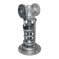
Design and principle of operation
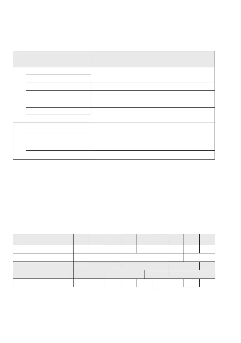
Table2: Max. permissible pressure at actuator
Set point ranges
Max. perm. pressure above the set point adjusted at the
actuator
Diaphragm actuator
0.05to0.25bar
0.6bar
0.1to0.6bar
0.2to1.2bar 1.3bar
0.8to2.5bar 2.5bar
2to5bar 5bar
4.5to10bar
10bar
8to16bar
Bellows actuator
2to6bar
6.5bar
5to10bar
10to22bar 8bar
20to28bar 2bar
Themaximumpermissiblepressureattheactuatordependsonthecurrentlyadjustedset
point. Add the value listed in the table to it.
Example:
Setpointrange:0.2to1.2bar,adjustedsetpoint:0.8bar
Max. permissible pressure atactuator: 0.8bar+1.3bar=2.1bar
Table3: K
VS
coefcients and x
FZ
values · Terms for noise level calculation according to
VDMA 24422 (edition 1.89)
Valve size DN 15 20 25 32 40 50 65 80 100
K
VS
1)
·Standardversion 4.0 6.3 8.0 16 20 32 50 80 125
x
FZ
0.5 0.45 0.4 0.35
K
VS
1)
·Specialversion 1.0 1.0·4.0 4.0·8.0 32
2)
80
x
FZ
0.6 0.5 0.45 0.4
K
VS
1)
·Withowdivider 3.0 5.0 6.0 12 15 25 38 42 66
1)
K
VS
≤4:valvewithoutbalancingbellows
2)
Max.permissible∆p:25bar

 Loading...