EB 8222-1 EN 3-7
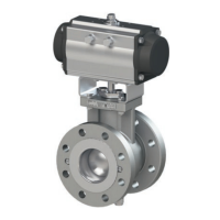
Design and principle of operation
Dimensions and weights
Dimensions in mm · Weights in kg
Table3-2: Dimensions for Type3310 Valve
Valve
NPS 1 1½ 2 3 4 6 8 10 12
DN 25 40 50 80 100 150 200 250 300
Face-to-face
dimension ac-
cording to
DINEN558-2
Series36 or
ISA75.08.02
Standard – Form B1 – Raised
face (DIN)
L
(Type21)
102 114 124 165 194 229 243 297 338
DEM – Form C – Tongue (DIN)
DEF – Form D – Groove (DIN)
SEM – Form E – Male face (DIN)
SEF – Form F – female face (DIN)
RF – Raised Face (ASME)
LFF – Large Female Face (ASME)
L 112 124 134 175 204 239 253 307 348
SFF – Small Female Face (ASME)
LGF – Large Groove Face (ASME)
SGF – Small Groove Face (ASME)
LMF – Large Male Face (ASME)
L 116 128 138 179 208 243 257 311 352
SMF – Small Male Face (ASME)
LTF – Large Tongue Face (ASME)
STF – Small Tongue Face (ASME)
Shaft end diameter Ød 16 16 16 16 25 25 36 36 36
Dimensions of square drive on shaft end SW
1)
12 12 12 12 19 19 27 27 27
Flange connection according to
DINENISO5211
TypeSRP/DAP
(AIRTORQUE)
F05
VK14
2)
• • • – – – – – –
F07
VK17
2)
• • • • – – – – –
F10
VK22
2)
– – • • • • – – –
F12
VK27
2)
– – – – • • • • •
F14
VK36
2)
– – – – • • • • •
F16
VK46
2)
– – – – – – • • •
SAMSON
Type3278
F05 Ø16 • • • – – – – – –
F07 Ø16 • • • • – – – – –
F10 Ø25 – – – – • • – – –
F12 Ø25 – – – – • • – – –
Other dimen-
sions
A 107 117 126 145 170 206 254 281 281
B
72.2
82.2
91.2
110.2
135.2
171.2
198.7
227.2
227.2
C 50 50 50 50 55 55 80 80 80
TypeSRP/DAP (AIRTORQUE)
E
15 15 15 18 23 23 35 35 35
SAMSON Type3278 31 31 31 34.3 49.2 49.2 – – –
Standard insulating section F 170 170 170 170 253 253 253 253 253
G 100 100 84 84 130 130 150 150 150
H – – 34 55 58 58 84 84 84
ØI 14 14 10.5 10.5 13 13 17 17 17
ØJ 63 63 63 63 78 78 100 100 100
1)
SW = Width across ats
2)
VK = Square drive