5-6 EB 8222-1 EN
Installation
5.3 Installing the device
The activities listed below are necessary to
install the valve and before it can be started
up.
Risk of valve damage due to excessively
high or low tightening torques.
Observe the specied torques when tighten-
ing control valve components. Excessive
tightening torques lead to parts wearing out
more quickly. Parts that are too loose may
cause leakage.
Î Observe the specied tightening torques
(uAB0100).
Risk of valve damage due to the use of un-
suitable tools.
Î Only use tools approved by SAMSON
(uAB0100).
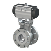
5.3.1 Mounting the actuator
onto the valve
See Fig.5-1 and Fig.5-2
Depending on the version, SAMSON control
valves are either delivered with the actuator
already mounted on the valve or the valve
and actuator are delivered separately. When
delivered separately, the valve and actuator
must be assembled together on site.
a) Type3310Valvewith
TypeSRPActuator
In the standard actuator version (SRP = sin-
gle-acting with spring return mechanism),
the spring return mechanism is designed to
close clockwise when there is no signal pres-
sure.
If you require a different direction of rotation
or a double-acting actuator (DAP = double-
acting without spring return mechanism), this
specication must be submitted on ordering
the actuator.
Table5-1: Type3310/SRP
Fail-safe ac-
tion
Direction of rotation of the ac-
tuator shaft caused by the
spring force
Fail-close Clockwise
Fail-open Counterclockwise
The square drive allows the actuator to be
mounted on the segmented ball valve offset
at angles of 90° in such a way that it is ei-
ther mounted onto the segmented ball valve
in the vertical or horizontal position to meet
the installation requirements.
Fail-close
1. Place the segmented ball (7) of the valve
in the CLOSED position (0° angle of ro-
tation).
2. Fasten the yoke (2) to the ange of the
valve shaft (12) using two or four screws
(depending on the valve size).
NOTICE
!
NOTICE
!
Note