EB 8222-1 EN 5-7
Installation
3. If necessary, place the shaft adapter on
the valve shaft (12). Slide the actuator
over the adapter or valve shaft (12) and
fasten it onto the yoke (2) with four
screws. There must be no clearance be-
tween the actuator and valve shaft (12)/
shaft adapter. If necessary, insert thin
wedges (see Fig.5-3 and the 'Accesso-
ries' section in the Annex).
4. For the actuator's standard direction of
rotation, adjust the stop bolt B to the
point where the valve is completely
closed and align the markings on the
valve shaft (12) and packing gland (15).
5. Lock the position of the stop bolt B with
the lock nut.
6. Apply a signal pressure to the signal
pressure connection which corresponds
to the number of actuator springs (see
actuator nameplate).
7. Turn the stop bolt A until the segmented
ball stops at an opening angle of 90°.
8. Lock the position of the stop bolt A with
the lock nut.
Fail-open
1. Place the segmented ball (7) of the valve
in the OPEN position (90° angle of rota-
tion).
2. Fasten the yoke (2) to the ange of the
valve shaft (12) using two or four screws
(depending on the valve size).
3. If necessary, place the shaft adapter on
the valve shaft (12). Slide the actuator
over the adapter or valve shaft (12) and
fasten it onto the yoke (2) with four
screws. There must be no clearance be-
tween the actuator and valve shaft (12)/
shaft adapter. If necessary, insert thin
wedges (see Fig.5-3 and the 'Accesso-
ries' section in the Annex).
4. For the actuator's standard direction of
rotation, adjust the stop bolt A to the
point where the valve is completely open
at 90° and align the markings on the
valve shaft (12) and packing gland (15).
5. Lock the position of the stop bolt A with
the lock nut.
6. Apply a signal pressure to the signal
pressure connection which corresponds
to the number of actuator springs (see
actuator nameplate).
7. Adjust the stop bolt B to the point where
the segmented ball (7) completely closes
the valve and align the markings on the
valve shaft (12) and packing gland (15).
8. Lock the position of the stop bolt B with
the lock nut.
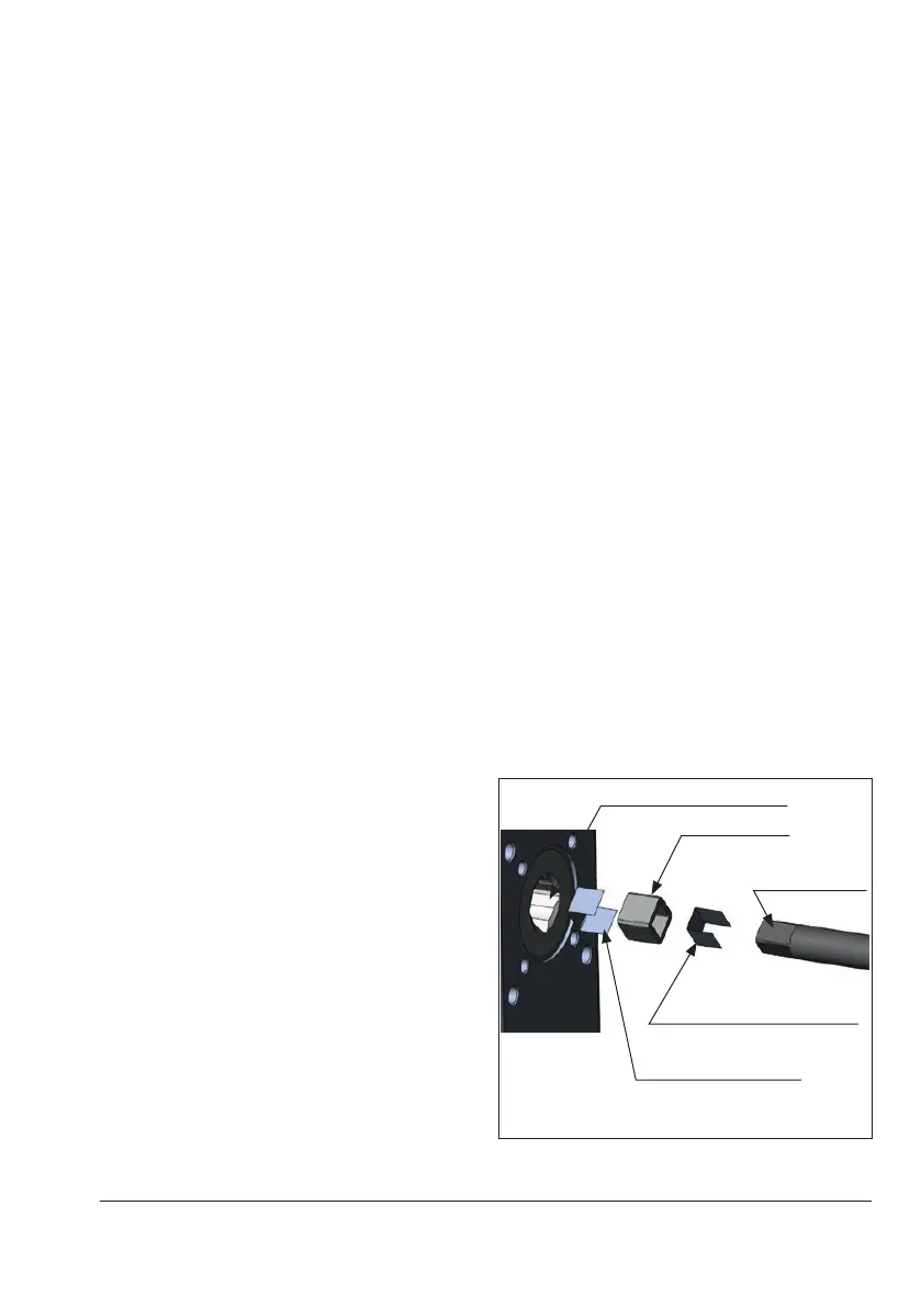
Actuator square drive (female)
Shaft adapter
Valve shaft
square drive
(male)
Wedge between actuator
and shaft adapter
Wedge between valve
shaft and shaft adapter
Fig.5-3: Wedge between valve shaft, shaft
adapter and actuator