5-8 EB 8222-1 EN
Installation
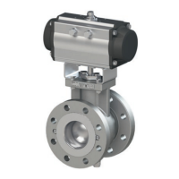
b) Type3310Valvewith
Type3278Actuator
Mount the actuator onto the body ange 1
or 2 depending on the characteristic and
fail-safe position.
'1' or '2' is cast on the corresponding side of
the body.
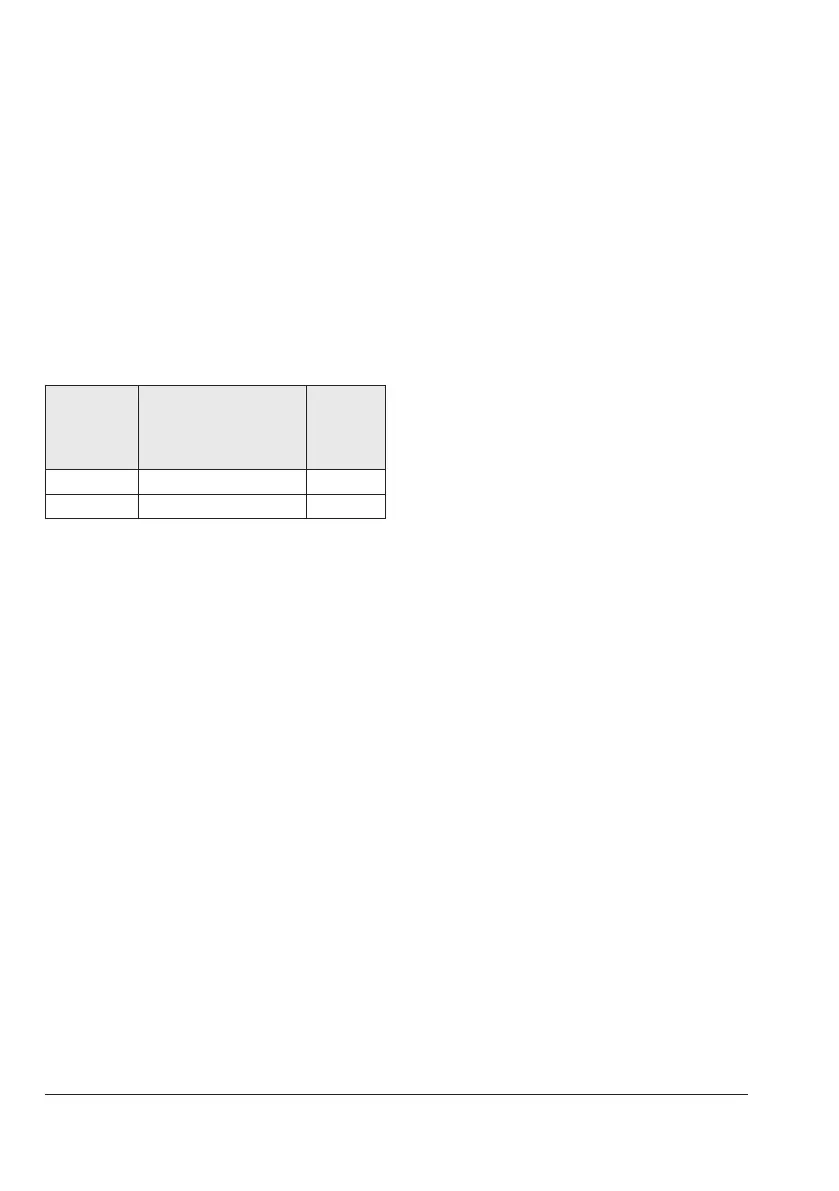
Table5-2: Type3310/3278
Fail-safe
action
Direction of rotation of
the actuator shaft
caused by the spring
force
Body
ange
Fail-close Clockwise 2
Fail-open Counterclockwise 1
The four feather key notches on the actuator
shaft arranged every 90° allow the rotary
actuator to be mounted on the segmented
ball valve offset at angles of 90° in such a
way that it is either in the vertical or horizon-
tal position to meet the installation require-
ments.
Fail-close
1. Completely undo both stop bolts on the
rotary actuator. Start to tighten the stop
bolt 2 until the grooves of the actuator
shaft are aligned with the actuator axis
horizontally or vertically.
2. Place the segmented ball (7) of the valve
in the CLOSED position (0° angle of ro-
tation).
3. Fasten the yoke (2) to the ange of the
valve shaft (12) using two or four screws
(depending on the valve size).
4. Slide the actuator over the valve shaft
(12) and fasten it onto the yoke (2) with
four screws.
5. Undo the stop bolt 2 again.
6. Adjust the stop bolt 2 to the point where
the valve is completely closed and align
the markings on the valve shaft (12) and
packing gland (15).
7. Apply a supply pressure required for the
spring range (see actuator nameplate) to
the loading pressure connection to open
the valve.
8. Start to tighten the stop bolt 1 until the
segmented ball (7) of the valve is in the
OPEN position (90° angle of rotation).
9. Lock the position of both stop bolts with
the lock nuts.
Fail-open
1. Completely undo both stop bolts on the
rotary actuator. Start to tighten the stop
bolt 1 until the grooves of the actuator
shaft are aligned with the actuator axis
horizontally or vertically.
2. Place the segmented ball (7) of the valve
in the OPEN position (90° angle of rota-
tion).
3. Fasten the yoke (2) to the ange of the
valve shaft (12) using two or four screws
(depending on the valve size).
4. Slide the actuator over the valve shaft
(12) and fasten it onto the yoke (2) with
four screws.
5. Undo the stop bolt 1 again.
6. Apply a supply pressure required for the
spring range (see actuator nameplate) to