PCB Diagram _ 55
6. PCB DIAGRAM
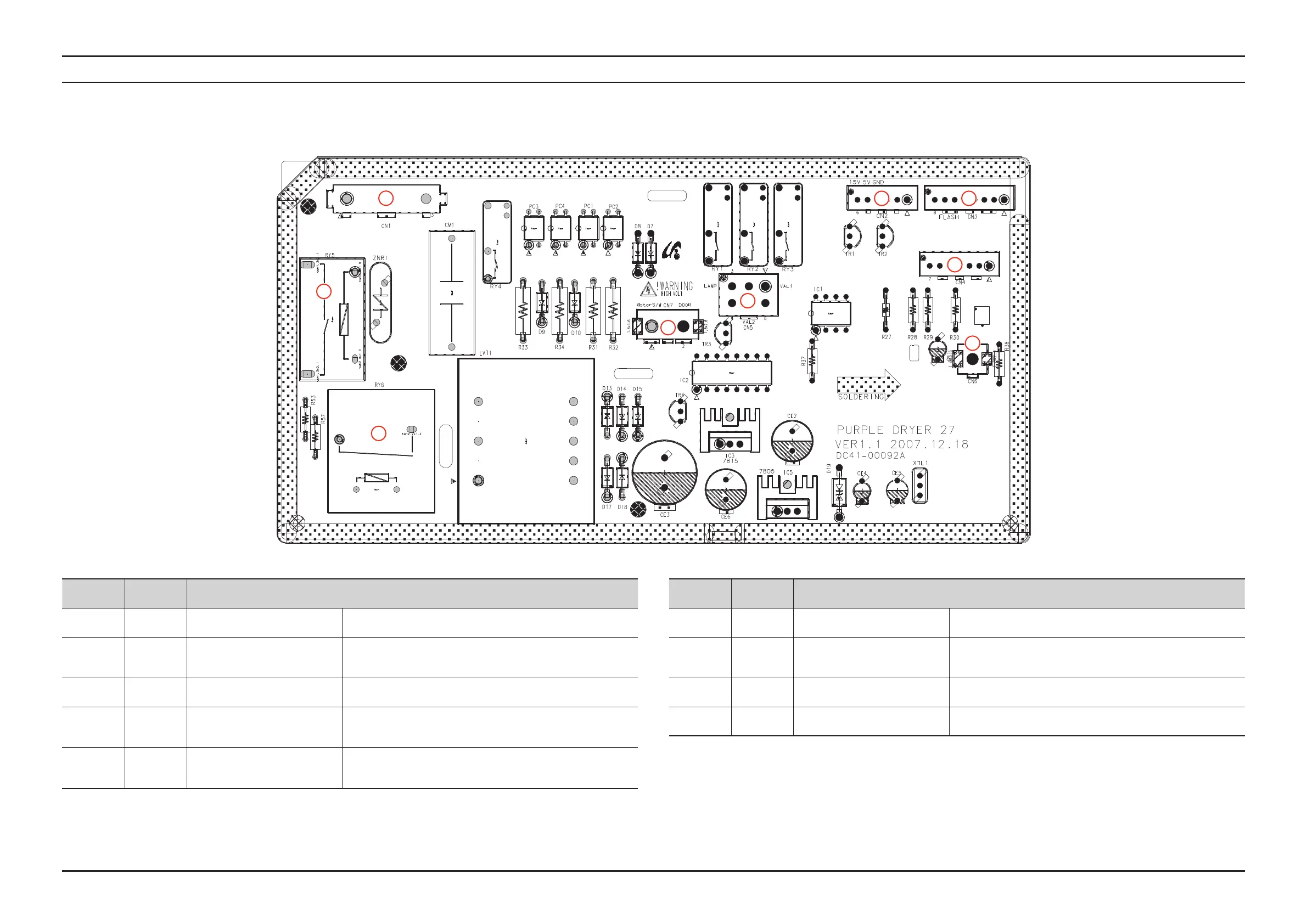
6-1. MAIN PCB
Location Part No. Function
1 CN1 AC CONNECTOR Supplies AC power to the PBA.
2 CN2
SUB PBA COMMUNICATION
CONNECTOR
The connector that controls communications with the Sub PBA
corresponding to the Display.
3 CN3 MICOM FLASH CONNECTOR The connector that writes software onto the Micom.
4 CN4 SENSOR CONNECTOR
Connects the temperature sensor in order to detect the
temperature of the heater.
5 CN5 VALVE CONNECTOR
It is connected to the Steam Valve(Steam Models Only) and the
Lamp of the Drive Block and controls the ON/OFF signal.
Location Part No. Function
6 CN6 SET GROUND CONNECTOR The plug connecting the Dryer Set and the ground of the PBA.
7 CN7 REACTOR CONNECTOR
The plug connecting the motor over-current protection reactor
and the motor control circuit.
8 RY5 MOTOR OPERATION RELAY The relay that turns the Main Motor on and off.
9 RY6 HEATER OPERATION RELAY The relay that turns the Heater on and off.
1
8
2 3
4
7
5
6
9
 Loading...