CHAPTER 2. Ошибка! Используйте вкладку "Главная" для применения 제목 1 к тексту, который должен здесь
отображаться.
2-8
© SAMSUNG Electronics Co., Ltd.
Board View
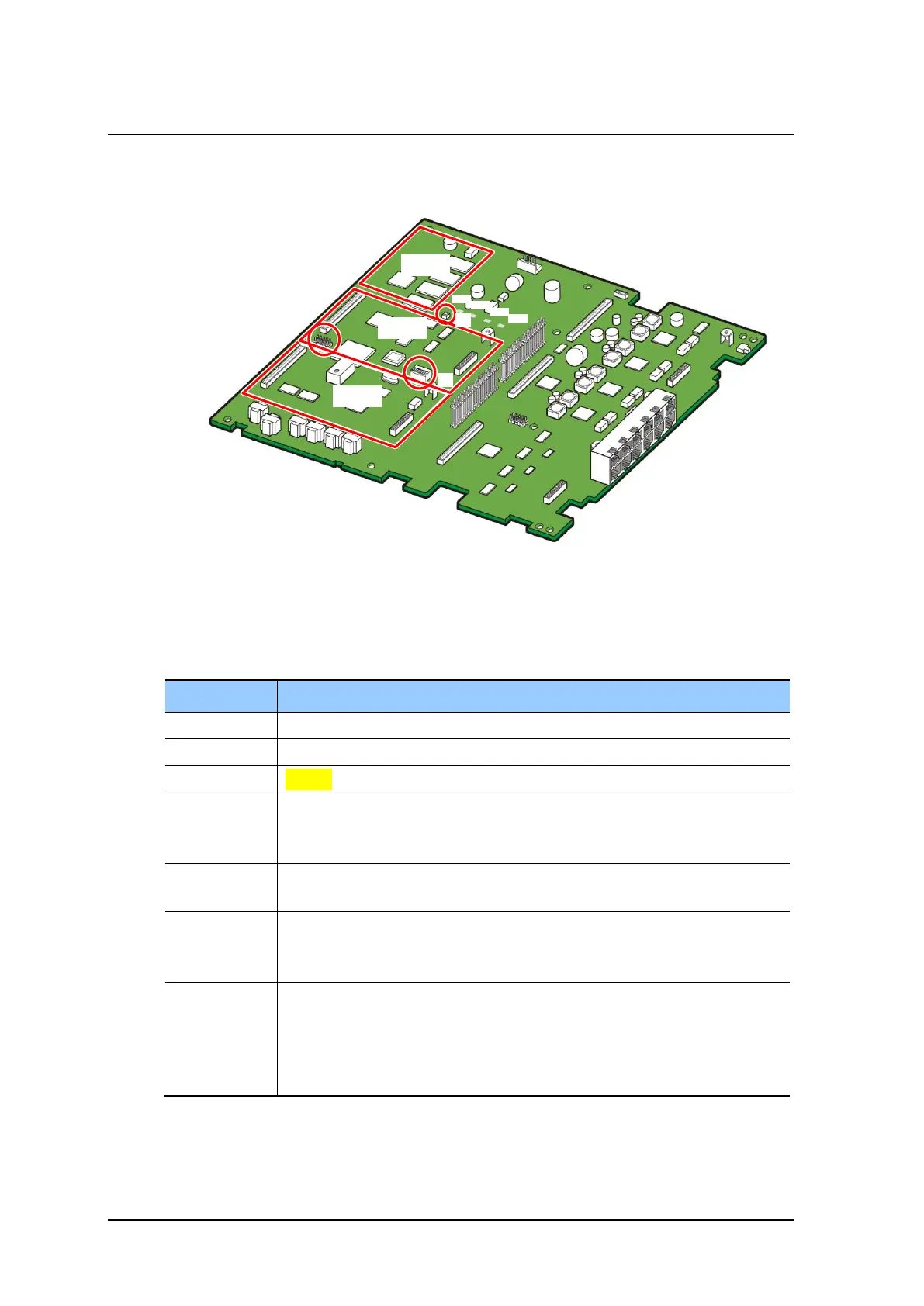
The appearance of the BMP (MAIN part) is as follows:
Figure 2.4 BMP (MAIN Part)
The functions of the parts of the BMP (MAIN part) are listed in the table below:
Table 2.7 BMP (MAIN Part) Configuration
An option board is mounted: RPM, 4DLM, 4SL2
An option board is mounted: 4DLM, 4SL2
Indicates the operation status of the system.
- Red: The system is booting.
- Green blinking: The system is operating normally.
Indicates the operation status of the LAN of the system.
- Indicates data sending and receiving are proceeding through the Ethernet port.
Indicates whether or not the NAND memory is being accessed.
- Off: The NAND memory is not being accessed.
- Blinking: The NAND memory is being accessed.
Indicates whether the PRM board is mounted and operating.
- Off: No PRM board is mounted.
- On: A PRM board is mounted but no line is connected.
- Blinking: A PRM board is mounted and is operating normally with an actual line
connected.