Model SA2-A Page 2 520-010-000 5/03
AIR INLET & PRIMING
For start-up, open an air valve approximately 1/2" to 3/4" turn. After the unit primes,
an air valve can be opened to increase flow as desired. If opening the valve increases
cycling rate, but does not increase flow rate, cavitation has occurred, and the valve
should be closed slightly.
For the most efficient use of compressed air and the longest diaphragm life, throttle
the air inlet to the lowest cycling rate that does not reduce flow.
A NOTE ABOUT AIR VALVE LUBRICATION
The Sandpiper pump’s pilot valve and main air valve assemblies are designed to
operate WITHOUT lubrication. This is the preferred mode of operation. There may be
instances of personal preference, or poor quality air supplies when lubrication of the
compressed air supply is required. The pump air system will operate with properly
lubricated compressed air supplies. Proper lubrication of the compressed air supply
would entail the use of an air line lubricator (available from Warren Rupp) set to deliver
one drop of 10 wt., non-detergent oil for every 20 SCFM of air the pump consumed at
its point of operation. Consult the pump’s published Performance Curve to determine
this.
It is important to remember to inspect the sleeve and spool set routinely. It should
move back and forth freely. This is most important when the air supply is lubricated.
If a lubricator is used, oil accumulation will, over time, collect any debris from the
compressed air. This can prevent the pump from operating properly.
Water in the compressed air supply can create problems such as icing or freezing
of the exhaust air causing the pump to cycle erratically, or stop operating. This can be
addressed by using a point of use air dryer to supplement a plant’s air drying
equipment. This device will remove excess water from the compressed air supply and
alleviate the icing or freezing problem.
ESADS: EXTERNALLY SERVICEABLE AIR
DISTRIBUTION SYSTEM
Please refer to the exploded view drawing and parts list in the Service Manual
supplied with your pump. If you need replacement or additional copies, contact your
local Warren Rupp Distributor, or the Warren Rupp factory Literature Department at
the number shown below. To receive the correct manual, you must specify the MODEL
and TYPE information found on the name plate of the pump.
MODELS WITH 1" SUCTION/DISCHARGE OR LARGER,
AND METAL CENTER SECTIONS:
The main air valve sleeve and spool set is located in the valve body mounted on
the pump with four hex head capscrews. The valve body assembly is removed from
the pump by removing these four hex head capscrews.
With the valve body assembly off the pump, access to the sleeve and spool set is
made by removing four hex head capscrews (each end) on the end caps of the valve
body assembly. With the end caps removed, slide the spool back and forth in the
sleeve. The spool is closely sized to the sleeve and must move freely to allow for proper
pump operation. An accumulation of oil, dirt or other contaminants from the pump’s
air supply, or from a failed diaphragm, may prevent the spool from moving freely. This
can cause the spool to stick in a position that prevents the pump from operating. If this
is the case, the sleeve and spool set should be removed from the valve body for
cleaning and further inspection.
Remove the spool from the sleeve. Using an arbor press or bench vise (with an
improvised mandrel), press the sleeve from the valve body. Take care not to damage
the sleeve. At this point, inspect the o-rings on the sleeve for nicks, tears or abrasions.
Damage of this sort could happen during assembly or servicing. A sheared or cut
o-ring can allow the pump’s compressed air supply to leak or bypass within the air
valve assembly, causing the pump to leak compressed air from the pump air exhaust
or not cycle properly. This is most noticeable at pump dead head or high discharge
pressure conditions. Replace any of these o-rings as required or set up a routine,
preventive maintenance schedule to do so on a regular basis. This practice should
include cleaning the spool and sleeve components with a safety solvent or equivalent,
inspecting for signs of wear or damage, and replacing worn components.
WARNING
Take action to prevent static sparking.
Fire or explosion can result, especially
when handling flammable liquids. The
pump, piping, valves, containers or other
miscellaneous equipment must be
grounded. (See page 6)
BEFORE OPERATION
Before pump operation, inspect all
gasketed fasteners for looseness caused
by gasket creep. Retorque loose
fasteners to prevent leakage. Follow
recommended torques stated in the card
attached to the new pump.
DANGER
Before doing any maintenance on the
pump, be certain all pressure is
completely vented from the pump,
suction, discharge, piping, and all other
openings and connections. Be certain
the air supply is locked out or made
non-operational, so that it cannot
be started while work is being done
on the pump. Be certain that approved
eye protection and protective clothing
are worn at all times in the vicinity
of the pump. Failure to follow
these recommendations may result
in serious injury or death.
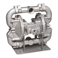
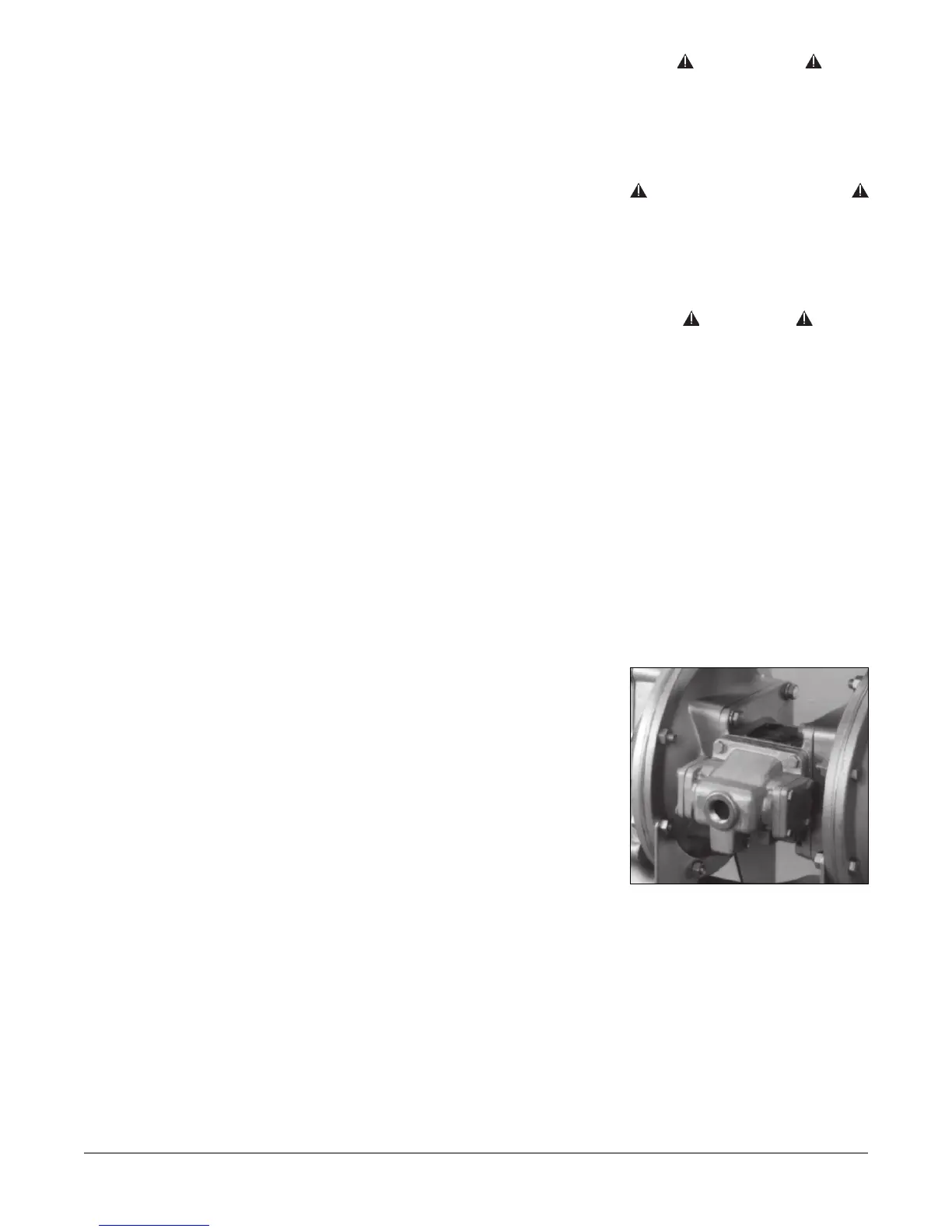
Air inlet.
 Loading...