520-010-000 5/03 Model SA2-A Page 3
To re-install the sleeve and spool set, lightly lubricate the o-rings on the sleeve with
an o-ring assembly lubricant or lightweight oil (such as 10 wt. air line lubricant).
Re-install one end cap, gasket and bumper on the valve body. Using the arbor press
or bench vise that was used in disassembly,
carefully press the sleeve back into the
valve body, without shearing the o-rings. You may have to clean the surfaces of the
valve body where the end caps mount. Material may remain from the old gasket. Old
material not cleaned from this area may cause air leakage after reassembly. Take care
that the bumper stays in place allowing the sleeve to press in all the way. Reinstall the
spool, opposite end cap, gasket and bumper on the valve body. After inspecting and
cleaning the gasket surfaces on the valve body and intermediate, reinstall the valve
body on the pump using new gaskets. Tighten the four hex head capscrews evenly
and in an alternating cross pattern.
AIR EXHAUST
If a diaphragm fails, the pumped liquid or fumes can enter the air end of the pump,
and be exhausted into the atmosphere. When pumping hazardous or toxic materials,
pipe the exhaust to an appropriate area for safe disposition.
This pump can be submerged if materials of construction are compatible with the
liquid. The air exhaust must be piped above the liquid level. Piping used for the air
exhaust must not be smaller than 1" (2.54 cm). Reducing the pipe size will restrict air
flow and reduce pump performance .When the product source is at a higher level than
the pump (flooded suction), pipe the exhaust higher than the product source to prevent
siphoning spills.
Freezing or icing-up of the air exhaust can occur under certain temperature and
humidity conditions. Use of an air dryer unit should eliminate most icing problems.
BETWEEN USES
When used for materials that tend to settle out or transform to solid form, the pump
should be completely flushed after each use, to prevent damage. Product remaining
in the pump between uses could dry out or settle out. This could cause problems with
valves and diaphragms at re-start. In freezing temperatures, the pump must be drained
between uses in all cases.
CHECK VALVE SERVICING
Valve inspection requires removal of (4)
3
/8" hex nuts. On the suction side the flange,
when removed, carries the valve and seat as an assembly. On the discharge side, the
valve and seat will stay with the diaphragm housing. Visual inspection and cleaning
is possible. If parts are to be replaced, remove the self locking nuts and all parts are
accessible.
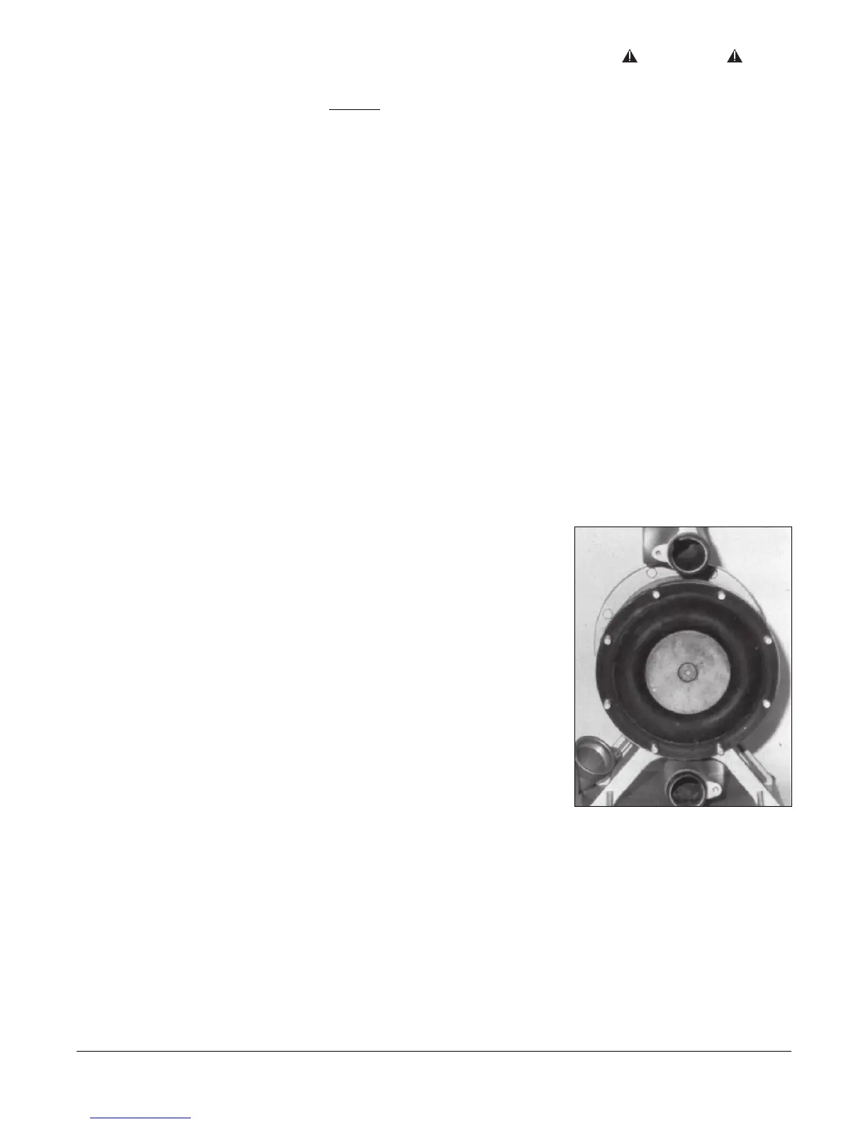
DIAPHRAGM SERVICING
Diaphragms can be inspected or the diaphragm assembly removed without
removing the suction and discharge flanges. Remove (8) nuts around the chamber
flange, and the housing assembly will pull off. Check valves can be inspected for
proper seating at this point as well as the diaphragm. Use care to keep foreign matter
from behind the diaphragm. The opposite diaphragm may be inspected by the same
procedure. If either diaphragm has to be replaced, follow closely these steps:
Pull the outer diameter of one diaphragm off the (8) capscrews. NOTE: One side only!
On the free diaphragm assembly, use a 3/8" allen wrench to turn the assembly
(diaphragm, plates and screw) loose from the shaft. Once the assembly has turned,
it will turn out by hand by use of the diaphragm. Now the opposite diaphragm assembly
and the drive shaft will pull free from the capscrews and pump
intermediate assembly. The interior components consisting of sleeve bearings, rod
seals, and pilot valve actuator bushings are now accessible for service if required.
Hold the shaft in a clamping device making sure to protect surface of shaft so as not
to scratch or mar it in any way. The diaphragm assembly will turn loose. To disassemble
the components, turn a 1/4"-20 capscrew by hand into the tapped hole in the inner
plate. This keeps the plate from turning while the socket head capscrew is removed.
To do this, place assembly in a vise so the two protruding ends of screws are loose
in the vise jaws (about 3/4" apart). Turn the center screw loose from the back plate and
the assembly will come apart.
CAUTION
In the event of diaphragm rupture,
pumped material may enter the air end
of the pump, and be discharged into the
atmosphere. If pumping a product which
is hazardous or toxic, the air exhaust
must be piped to an appropriate area for
safe disposition.
Diaphragm.
 Loading...