INSTALLATION – GENERAL
PIPE FITTINGS
The connection points to the heating system are in 22mm copper pipe on 120, 150, 170 and 210 litre units. On units 250
litres and above the primary ow connection is 28mm, the ow connections to central heating (CH) zones 22mm and the
domestic hot water (DHW) return connection 22mm copper pipe. The use of appropriately sized COMPRESSION FITTINGS
is recommended when connecting to the PremierPlus SystemFit pipes. Solder ttings can be used, but extreme care must
be taken to ensure the plastic coating of the unit casing is not damaged by heat. Push t type ttings can be used for
connection to the copper pipes.
The inlet connection to the cold water combination valve is 22mm compression. The PremierPlus SystemFit outlet tting
is suitable for connection to 22mm o/dia pipe (compression nut and olive supplied). The outlet is also threaded 3/4” BSP
male parallel should threaded pipe connections be preferred.
COLD FEED
A 22mm cold water supply is recommended, however, if a 15mm (1/2”) supply exists which provides sufcient ow, this may
be used. More ow noise may be experienced from small bore pipes due to the increased water velocity through them.
A stopcock or servicing valve should be incorporated into the cold water supply to enable the PremierPlus SystemFit and its
associated controls to be isolated and serviced.
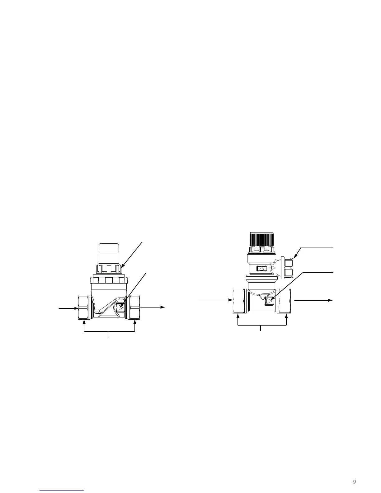
PRESSURE REDUCING VALVE (Fig 2 below)
The 3.5 bar pressure reducing valve can be connected anywhere on the cold water mains supply prior to the PremierPlus
SystemFit unit. There is no requirement to site it close to the unit, it can be located at a point where the mains supply
enters the premises if this is more convenient but you must install a non-return valve just after the reducing valve for ease
of maintenance.
Fig 2 - Pressure reducing valve Fig 3 - Pressure relief valve (6 bar)
PRESSURE RELIEF VALVE (Fig 3 above)
Should a balanced pressure cold water supply be required to cold water outlets such as thermostatic shower mixer valves
or combination taps, the cold water balanced draw off connection should be taken from between the pressure reducing
valve and the pressure relief valve (see Fig 3 above). Branches to cold drinking water outlets should be taken directly from
the mains supply.
EXPANSION VESSEL
The expansion vessel accommodates expansion that results from heating the water inside the unit. The expansion vessel is
pre-charged at 3.5 bar. The expansion vessel must be connected between the expansion valve (see Fig. 3 above) and the
PremierPlus SystemFit cylinder. The location of the expansion vessel should allow access to recharge the pressure as and
when necessary, this can be done using a normal car foot pump. It is recommended that the expansion vessel is adequately
supported. An expansion vessel wall mounting bracket is supplied for this purpose and should be tted.
TUNDISH
The tundish must not be installed directly over any electrical device.
9
Outlet to cylinder