-9-
■ Mechanical disassemblies
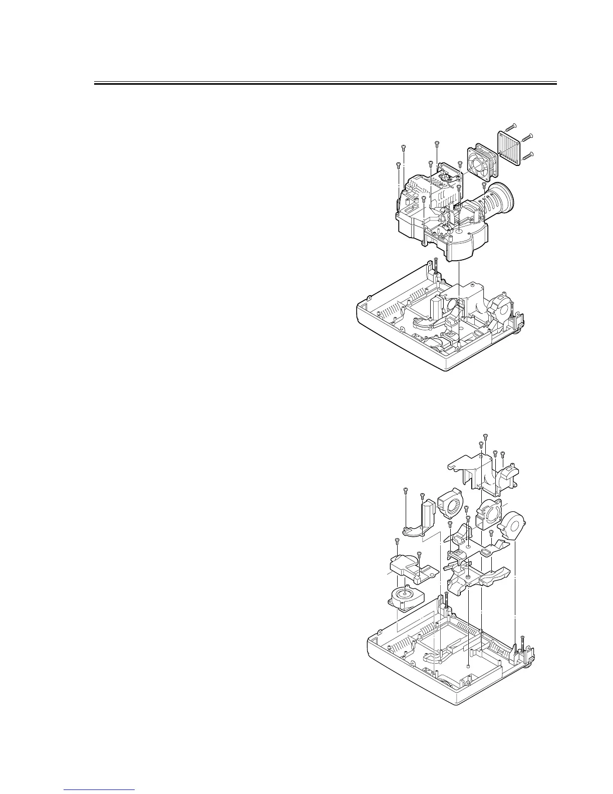
7. OPTICAL UNIT, FAN (FN901) AND LOUVER REMOVAL
1. Remove eight screws and remove Optical unit.
2. Remove three screws and remove Fan(FN901) and
louver.
See figure right.
8. AIR DUCTS AND FANS REMOVAL
1. Remove four screws-A and remove Duct-FR and
FN905.
2. Remove two screws-B and remove Duct-PBS and
FN906.
3. Remove three screws-C and remove Duct-TOP and
FN902.
4. Remove two screws-D and remove Duct-TOP-Green
and FN904.
5. Remove screw-E and remove Duct-BTM.
See figure right.
 Loading...