Note:
Do not replace the LCD panel
separately otherwise it can
not obtain proper picture.
-5-
KEY No.
DESCRIPTION
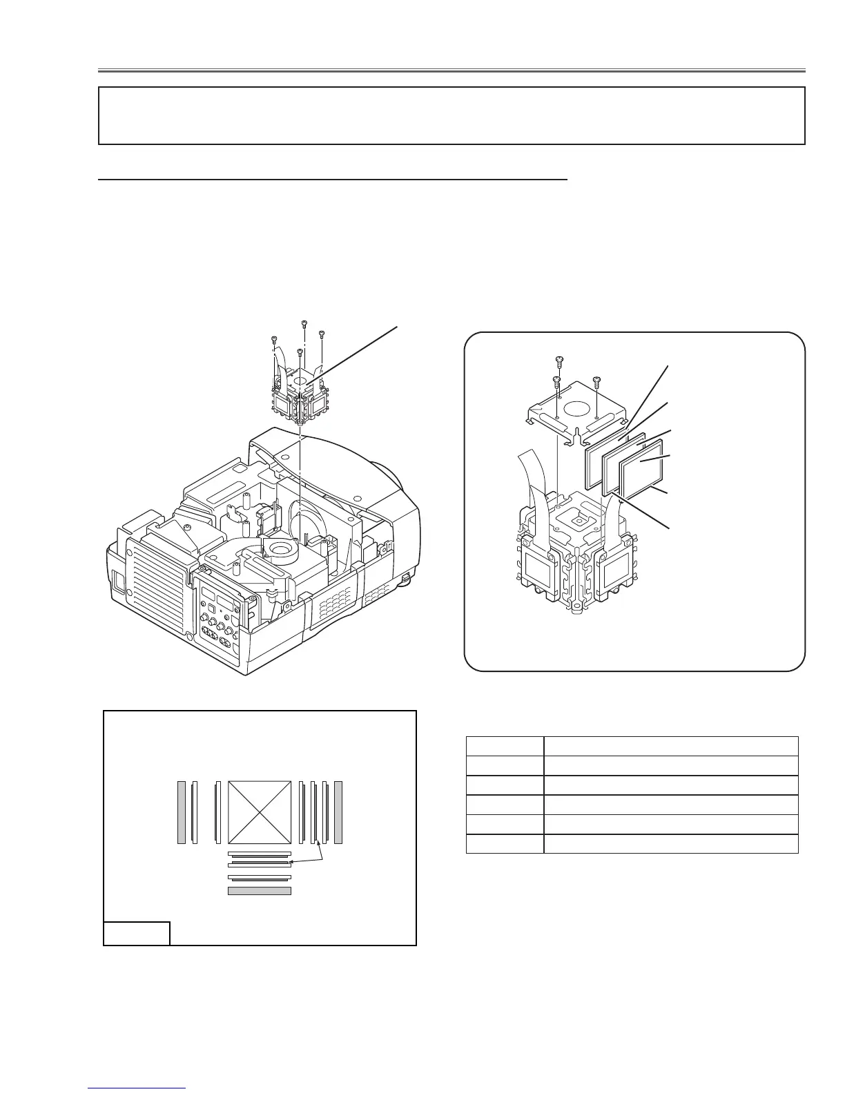
1 PRISM ASSEMBLY
2 POLARIZED GLASS OUT
3
PRE-POLARIZED GLASS OUT(*2)
4 WIDE VIEW GLASS
5 LCD PANEL
(*2) PRE-POLARIZED GLASS
The printed marker comes top side, and the glass
should be placed the sheet attached side comes
as shown in Fig.4-3.
Fig.4-3
* Following assemblies differ from previous assemblies for chassis No. MR3-XP5500, others are the same;
- The direction of the phase sheet on the pre-polarized glass has been changed.
1 Remove 4 hex screws A and take the LCD/Prism ass’y off upward.
2 Remove 3 screws B and take the Glass Holder, and then pull the polarized
Glass-Out and the wide view glass upwards off. These glasses are mount-
ed for R, G and B LCD panels respectively.
Note:
To avoid the CG and focus alignments slipping off, please be careful to han-
dle the LCD/Prism ass'y.
LCD Panel/Prism Ass’y
Fig.4-
1
Polarized Glass-Out and Wide view Glass removal
A
A
A
*2 Glasses should be placed as the
sheet attached side comes as
shown in Fig.4-3.
Fig.4-
2
B
B
B
Pre-Polarized
Glass-Out (*1)
Phase Sheet
Wide view Glass
Phase Sheet
Polarized Glass-
Out
*1 Pre-polarized Glass-
Out should be placed
into the Green and
Blue LCD panels.
Phase Sheet (*1)
■ Optical Parts Disassemblies