-14-
Mechanical Disassembly
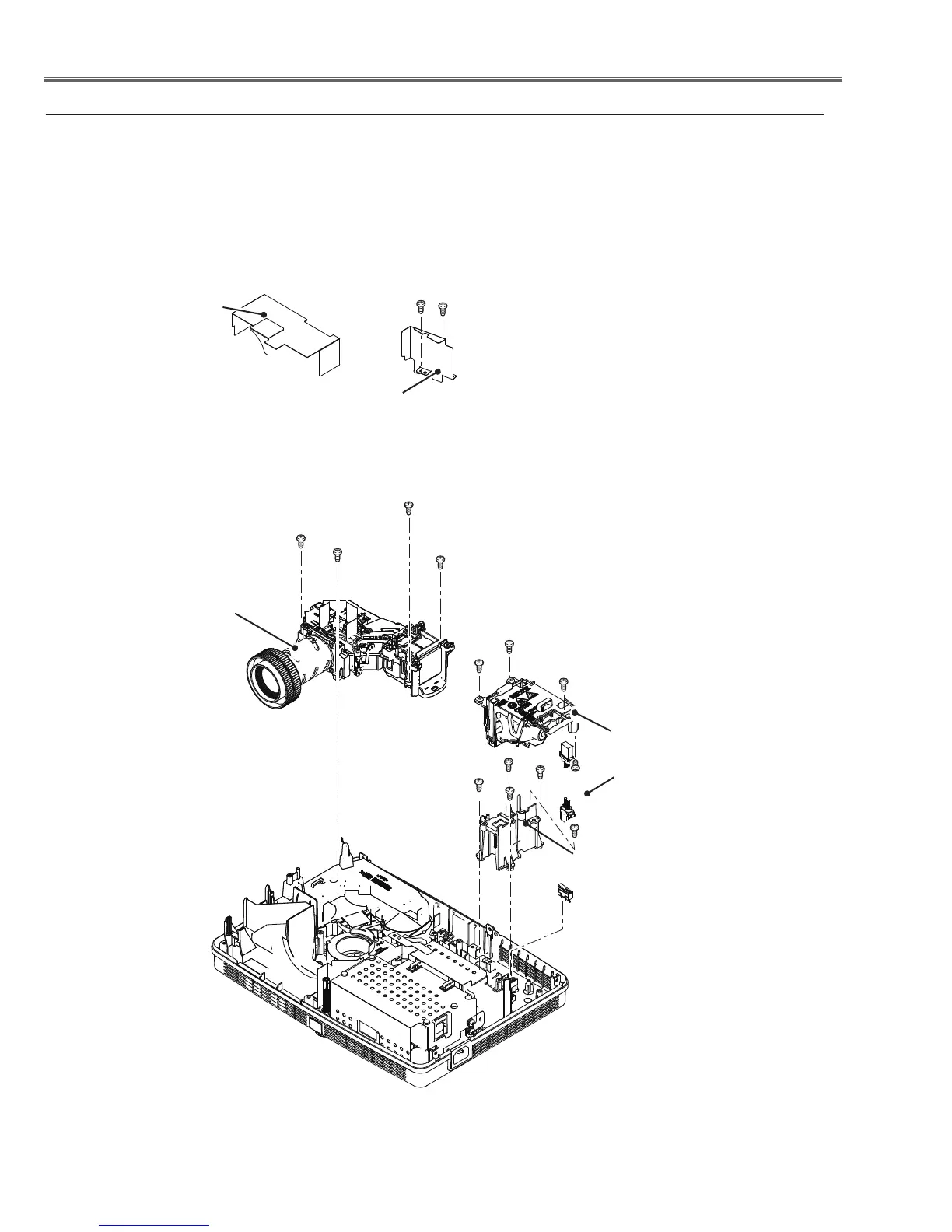
1. Remove the Lens spacer sheet-top. Remove 2 screws A(M3x8) to remove the
Optical back shield.
2. Remove 3 screws B(M3x7) to remove the Lamp A'ssy. Remove 4 screws
C(T3x10) to remove the Optical Unit, Remove 4 screws D(T3x8) and 2 screws
E(T3x8) to remove the Lamp holder and Ballast socket.
3. Remove the lamp cover switch(SW902).
Fig.3
c Optical Unit, Lamp A'ssy and SW902 removal
Optical Unit
Ballast socket
B (M3x7)x3
Lamp holder
C (T3x10)X4
Optical back shield
E(T3x8)x2
Lens spacer
sheet-top
A (M3x8)X2
A
C
C
C
B
D
D
D (T3x8)x4
D
B
E
Lamp Ass'y
SW902
 Loading...