J
Joseph AndersonAug 10, 2025
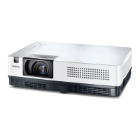
What to do if the LAMP REPLACE indicator lights yellow on my Sanyo PLC-XR201 Projector?
- CcassandrahuntAug 10, 2025
If the LAMP REPLACE indicator on your Sanyo Projector lights up yellow, it means you should promptly replace the projection lamp with a new one. After replacing the lamp, remember to reset the lamp replacement counter.