-16-
Mechanical Disassembly
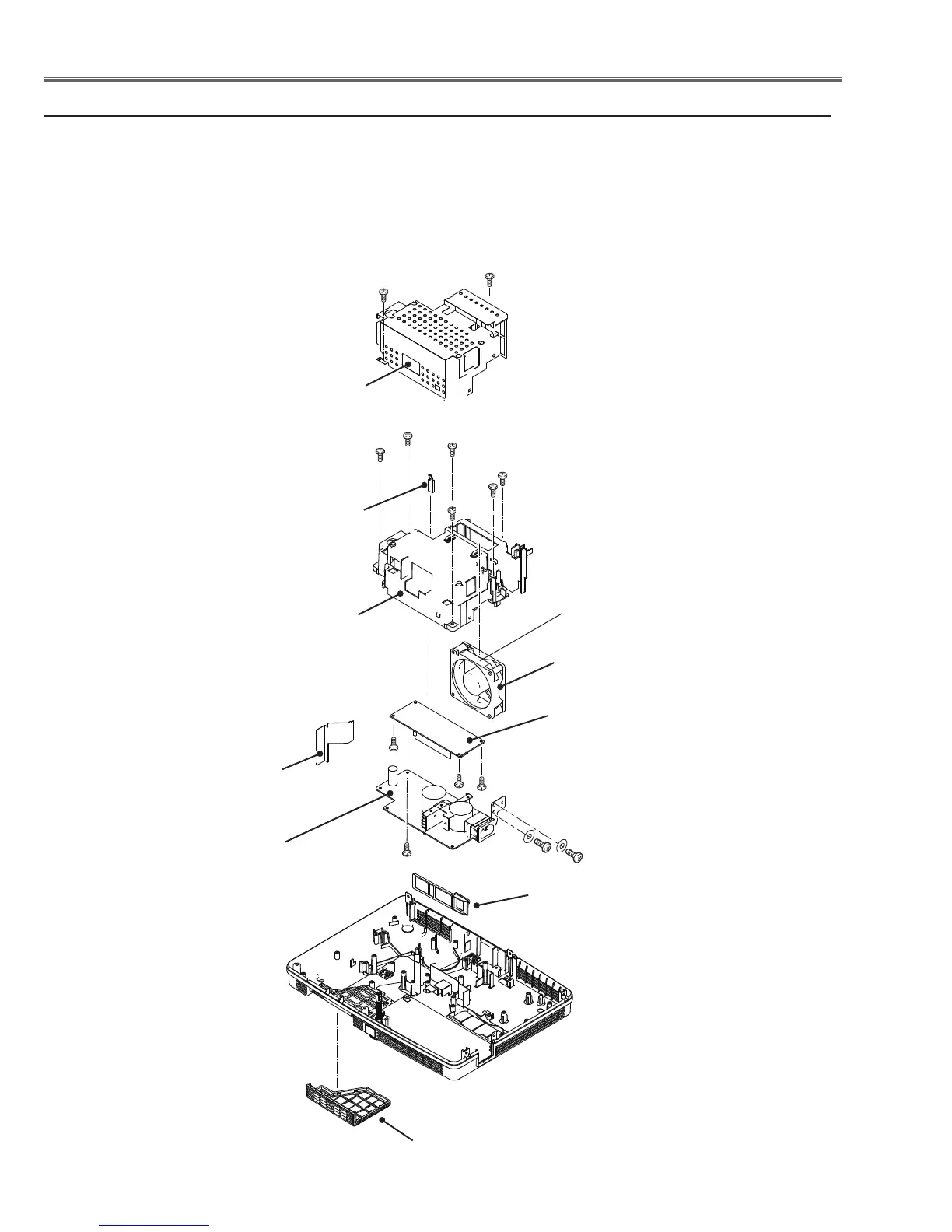
Fig.5
b Power board, Fan(FN002) and Filter removal
Power board
spacer sheet
1. Remove the Power board spacer sheet.
2. Remove 2 screws A(M3x8) and 2 screws B(M4x6) to remove the Power shield.
3. Remove the thermal switch(SW601). Remove 6 screws C(T3x8) to remove the Power board
holder and the fan(FN002).
4. Remove screw D(T3x8) to remove the Power board.
5. Remove 3 screws E(T3x8) to remove the Lamp Ballast.
6. Remove the Panel net front and Panel net back.
FN002
Power shield
C(T3x8)x6
C
Panel net front
Power board
A (M3x8)x2
A
Power board holder
C
C
C
C
Lamp Ballast
Panel net back
D(T3x8)
E(T3x8)x3
E
E
SW601
Note:
Please pay attention to the install
direction of SW601, the side with
text facing to the projector back.
B (M4x6)x2
B
The exhaust side facing
to the screening shield.
 Loading...