-15-
Mechanical Disassembly
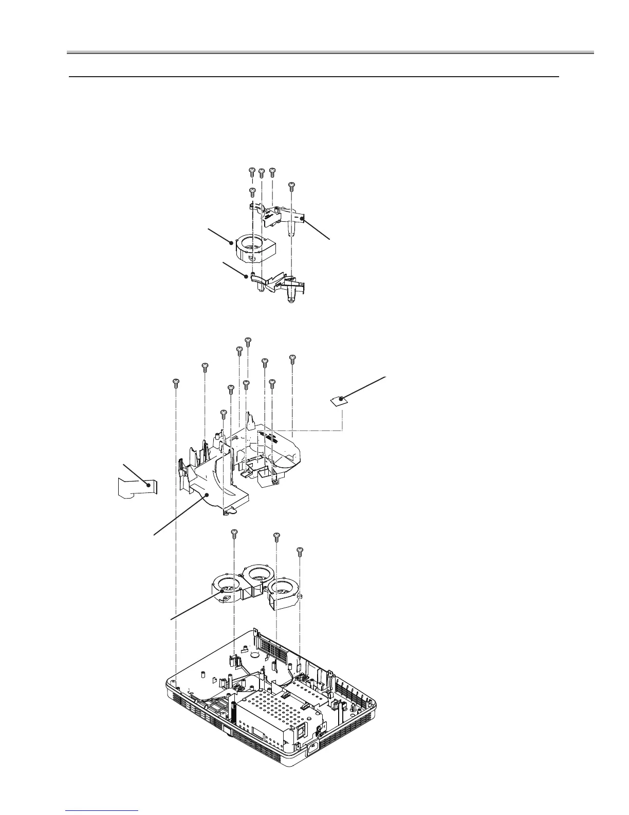
v Mounting Duct and fans(FN001, FN003, FN004, FN005) removal
Fig.4
FN004
1. Remove the Lens spacer sheet-left, remove 3 screws A(T3x8) and 2
screw B(T3x12) to remove the Lamp in fan duct top and bottom.
2. Remove 7 screws C(T3X8) and 3 screws D(T3x12) to remove the Mounting
duct top.
3. Remove 3 screws E(T3x12) to remove the fans(FN003, FN004 and FN005).
A (T3x8)x3
B(T3x12)x2
FN001
C
C
Lens spacer
sheet-left
A
A
Lamp in fan
duct bottom
Lamp in fan
duct top
C (T3x8)x7
D(T3x12)x3
D
D
C
C
C
C
C
Mounting
duct top
E(T3x12)x3
E
E
FN005
FN003
B
Spacer sheet-R
(only for KR5-XR20100)
 Loading...