-26-
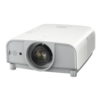
Electrical Adjustments
1. Receive the 16-step gray scale computer signal with
Computer 1 [Analog RGB] mode.
2. Enter the service mode.
3. Connect an oscilloscope to test point “TP531” (+) and
chassis ground (-).
4. Select group no. “5”, Item no. “11” and adjust the
black level to be maximum amplitude by changing the
Data value.
5. Connect an oscilloscope to test point “TP501” (+) and
chassis ground (-).
6. Select Item no. “12” and adjust the black level to be
maximum amplitude by changing the Data value.
7. Connect an oscilloscope to test point “TP561” (+) and
chassis ground (-).
8. Select Item no. “13” and adjust the black level to be
maximum amplitude by changing the Data value.
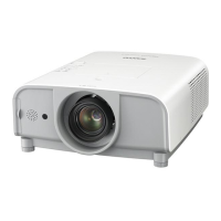
Pedestal Level
Black Level
Pedestal adjustment [PC]
4
1. Receive the 16-step gray scale computer signal with
Computer 1 [Analog RGB] mode.
2. Enter the service mode.
3. Connect an oscilloscope to test point “TP2531”(+)
and chassis ground (-).
4. Select group no. “5”, Item no. “7” and adjust the ampli-
tude “a” to be 2.0 ±0.1V by changing the Data value.
5. Select Item no. “6” and adjust the amplitude “b” to be
7.1 ±0.1V by changing the Data value.
(a)
(b)
GND
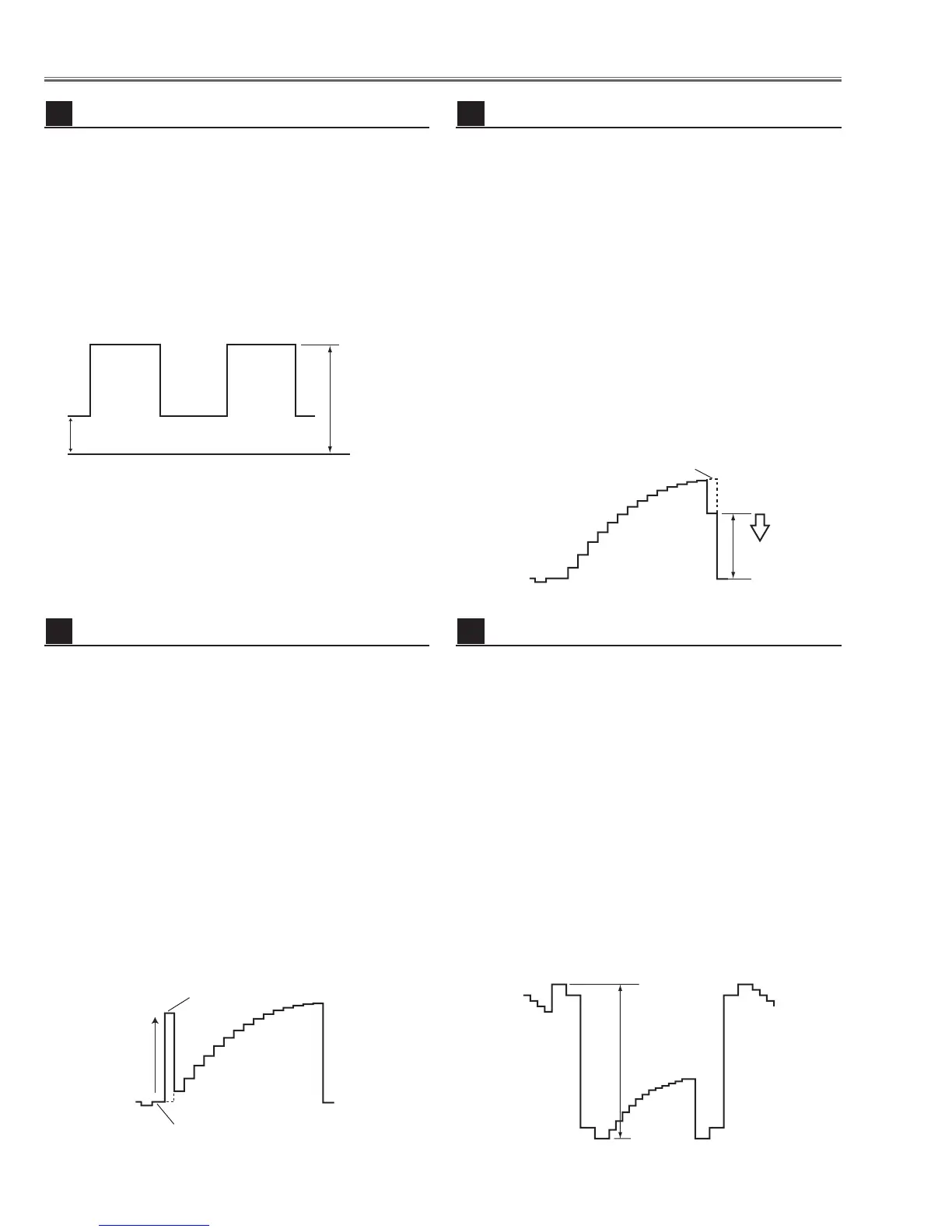
NRS adjustment
3
1. Receive the 16-step gray scale computer signal with
Computer 1 [Analog RGB] mode.
2. Enter the service mode.
3. Connect an oscilloscope to test point “TP531” (+)
and chassis ground (-).
4. Select group no. “5”, Item no. “3” and adjust the
amplitude “a” to be 10.0 ±0.1V by changing the
Data value.
5. Connect an oscilloscope to test point “TP501”(+)
and chassis ground (-).
6. Select Item no. “4” and adjust the amplitude “a” to be
9.25 ±0.1V by changing the Data value.
7. Connect an oscilloscope to test point “TP561”(+)
and chassis ground (-).
8. Select Item no. “5” and adjust the amplitude “a” to be
10.0 ±0.1V by changing the Data value.
(a)
black level
black level
Black Level adjustment [PC]
6
1. Receive the 16-step gray scale computer signal with
Computer 1 [Analog RGB] mode.
2. Enter the service mode.
3. Connect an oscilloscope to test point “TP531”(+)
and chassis ground (-).
4. Select group no. “4”, Item no. “3” and adjust the white
level to be minimum amplitude by changing the Data
value.
5. Connect an oscilloscope to test point “TP501”(+)
and chassis ground (-).
6. Select Item no. “4” and adjust the white level to be
minimum amplitude by changing the Data value.
7. Connect an oscilloscope to test point “TP561”(+)
and chassis ground (-).
8. Select Item no. “5” and adjust the white level to be
minimum amplitude by changing the Data value.
(a)
White Level
Video Gain adjustment [PC]
5

 Loading...