-25-
[Adjustment Condition]
● Input signal
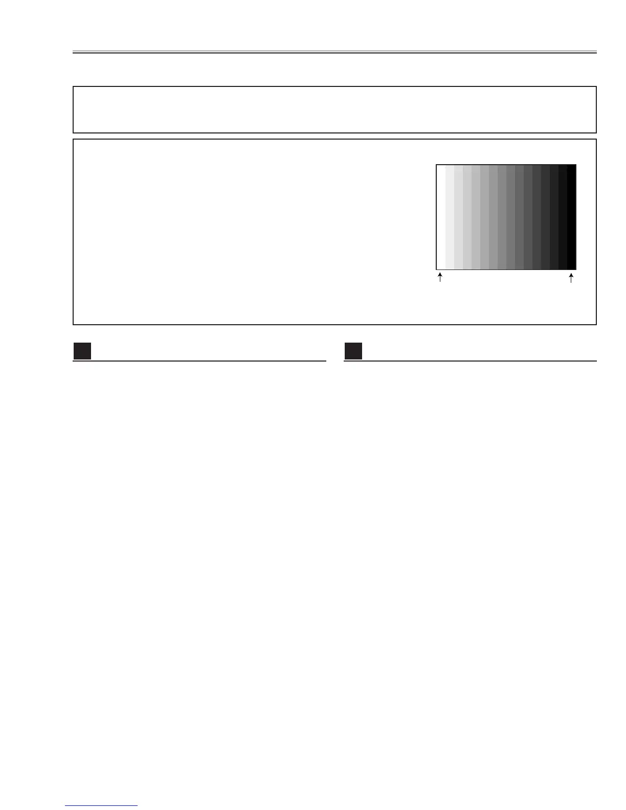
Video signal .......................... 1.0Vp-p/75Ω terminated, 16 steps gray
scale (Composite video signal)
Computer signal .................... 0.7Vp-p/75Ω terminated, 16 steps gray
scale pattern (XGA)
Component Video signal ...... 0.7Vp-p/75Ω terminated, 16 steps gray
scale (Component video signal with
480p or 1080i format)
● Picture control mode .............. “STANDARD” mode unless otherwise
noted.
Note:
* Please refer to “Service Adjustment Menu Operation” for entering the service mode and adjusting the service data.
● Circuit Adjustments
CAUTION: The each circuit has been made by the fine adjustment at factory. Do not attempt to adjust the follow-
ing adjustments except requiring the readjustments in servicing otherwise it may cause loss of per-
formance and product safety.
Electrical Adjustments
1. Receive the 16-step gray scale computer signal with
Computer 1 [Analog RGB] mode.
2. Enter the service mode.
3. Connect a digital voltmeter to test point “TP531”(+)
and chassis ground (-).
4. Select group no. “5”, Item no. “0” and adjust the volt-
age to be 7.50 ±0.1Vdc by changing the Data value.
5. Connect a digital voltmeter to test point “TP501”(+)
and chassis ground (-).
6. Select Item no. “1” and adjust the voltage to be 7.50
±0.1Vdc by changing the Data value.
7. Connect a digital voltmeter to test point “TP561”(+)
and chassis ground (-).
8. Select Item no. “2” and adjust the voltage to be 7.50
±0.1Vdc by changing the Data value.
Video Center adjustment
2
16 steps gray scale pattern
1. Set the lamp mode to “ECO” with the menu function.
2. Enter the service mode and select group no. “11” and
Item no. “5”. Set Data value to “1”.
3. Connect a digital voltmeter to test point “TPFAN1”(+)
and chassis ground (-).
4. Select group no. “11”, Item no. “86” and adjust the volt-
age to be 4.5 ±0.1Vdc by changing the Data value.
Select Item no. “87” and adjust the voltage to be 13.8
±0.1Vdc by changing the Data value.
5. Connect a digital voltmeter to test point “TPFAN2”(+)
and chassis ground (-).
6. Select Item no. “88” and adjust the voltage to be 4.5
±0.1Vdc by changing the Data value.
Select Item no. “89” and adjust the voltage to be 13.8
±0.1Vdc by changing the Data value.
7. Connect a digital voltmeter to test point “TPFAN3”(+)
and chassis ground (-).
8. Select Item no. “90” and adjust the voltage to be 4.5
±0.1Vdc by changing the Data value.
Select Item no. “91” and adjust the voltage to be 13.8
±0.1Vdc by changing the Data value.
9. Select group no. “11” and Item no. “5”. Set Data value
to “0”, and set the lamp mode to “Normal” with the
menu function.
Fan Voltage adjustment
1

 Loading...