-15-
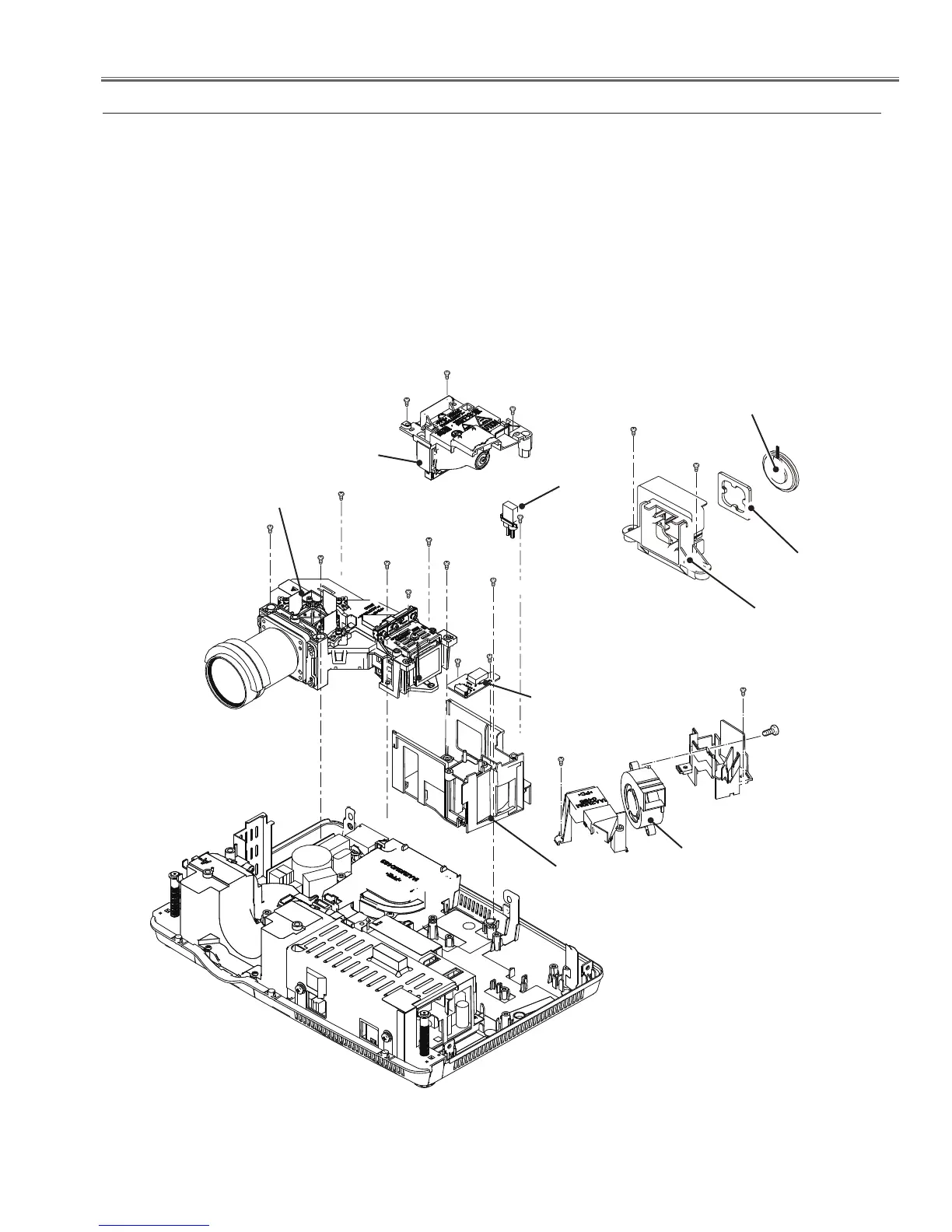
Mechanical Disassembly
1. Remove the 2 screws A (T3x8) to remove the speaker holder and the
Speaker (SP901).
2. Remove 2 screws B (T3x8) and screw C (T3x12) to remove the fan
(FN901).
3. Remove 3 screws D(M3x7) to remove the
Lamp unit (LP900).
4. Remove the 2 screws E (T3x6) to remove the CONNECT ID board.
5. Remove the screw F (T3x8) to disconnect the Ballast socket.
6. Remove 5 screws G (T3x8) and 3 screws H(T3x8) to remove the Optical
Unit and the Lamp holder.
Fig.3
3. Speaker(SP901), Fan (FN901),Lamp Unit(LP900) and Optical Unit removal
Optical Unit
Ballast socket
Speaker
(SP901)
E (T3x6)x2
Lamp
(LP900)
D (M3x7)X3
CONNECT ID
board
Lamp holder
D
D
E
F (T3x8)
A (T3x8)X2
A
Speaker holder
G (T3x8)X5
G
G
G
G
H(T3x8)X3
H
G
H
B (T3x8)X2
B
C (T3x12)
Fan (FN901)
Spacer
 Loading...