Replacement of Main Units
TD831077
VII-9
7
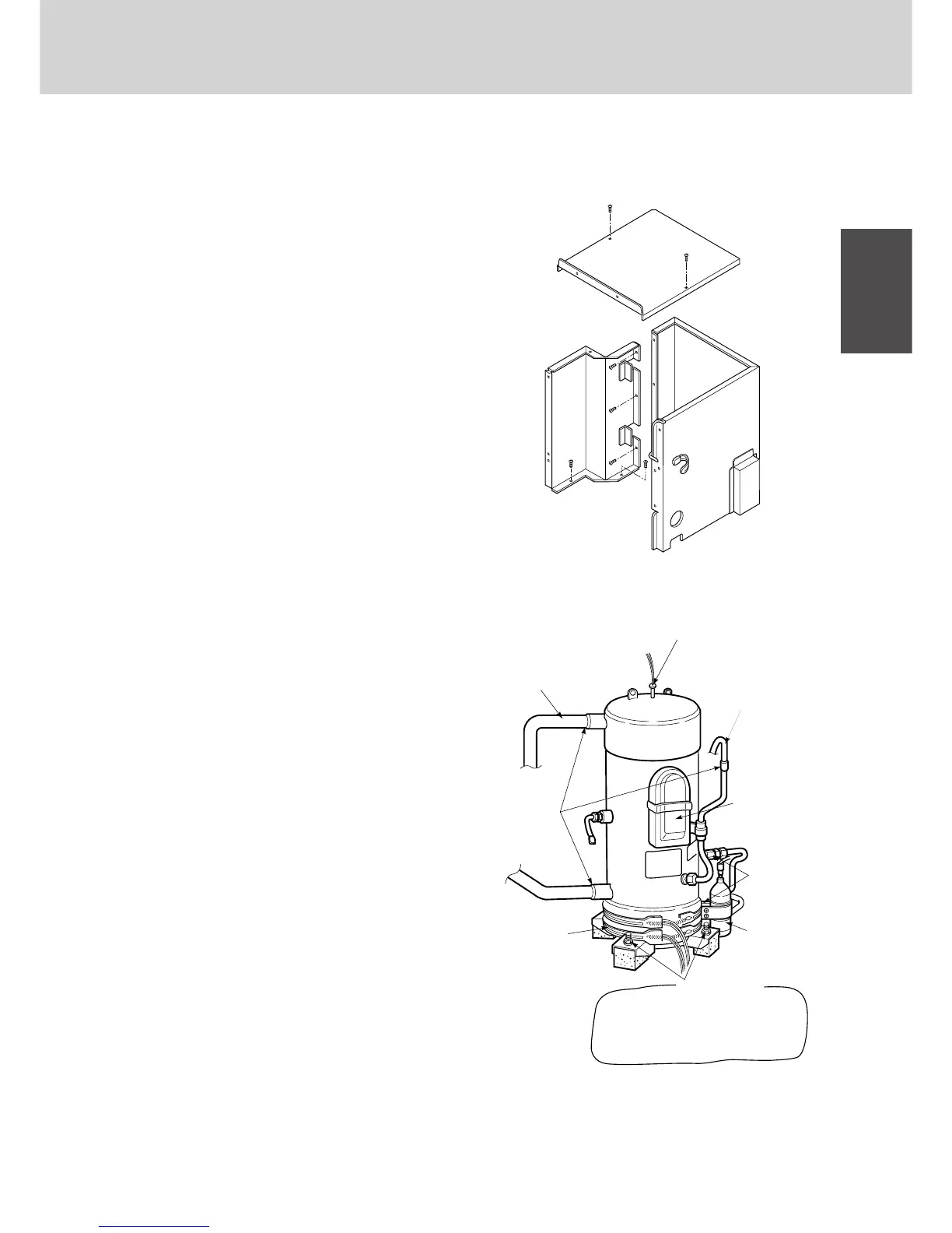
1. Compressors
(1) Replacing the compressor (Ref. Fig. 5, 6)
[Removal]
1. Remove the front panel.
2. Remove the electrical parts box.
3. Remove the part of the compressor cover.
¶ Disconnect the wires bundled together by the
clamper.
4. Remove the sound-proofing material which is
wrapped around the compressor.
5. Remove the cap over the compressor terminal
section, and disconnect the power and internal
terminals.
6. Remove the crankcase heater.
7. Disconnect the oil sensor lead wires from the PCB.
8. Draw out the discharge sensor at the top of the
compressor.
(Draw out the resin stopper.)
9. Remove the nuts with washers.
10. Proceed as instructed below to remove the oil from
the suction pipe.
¶ Remove the upper pipe flare of the oil sensor. If
oil oozes out, drain it off until no more comes
out. (Provide a pan to collect the oil.)
¶ After checking the above work, tilt the compres-
sor, remove the lower pipe flare of the oil sensor,
and then remove the oil sensor itself. (The oil
which was in the oil sensor will ooze out at this
point.)
¶ Adjust the angle of tilt, and drain off the liter or so
of oil inside the compressor. (It is OK if no oil
comes out.)
¶ Place the cap over the installation hole of the oil
sensor.
11. Prepare to remove the welded areas.
¶ Protect the plate, rubber, leads and clampers
around these areas.
12. Remove the three welded areas.
13. Lift and draw the compressor out toward you.
1872_M_I
Top panel
1873_M_I
Crankcase heater
Discharge pipe
Welded areas
Nut with washer
(×4)
Power terminal
Internal terminal
Flares
Oil sensor
Discharge sensor
Oil return pipe
Cloth
Fig. 5
Fig. 6
1-4. AD unit
 Loading...

