Do you have a question about the Sartorius MW1P and is the answer not in the manual?
General information about the service manual, scale operation, and safety measures for indicator maintenance.
Description of Sartorius Midrics scale configurations and required auxiliary service tools.
List of related operating instructions and documentation for Sartorius Midrics series.
Details on the front panel, keypad, display, and interfaces of Midrics 1/2 indicators.
Information on the Main PCB and Power PCB within the Midrics indicators.
Explanation of the menu access switch's function and its effect on A/D converter configuration.
Important safety note regarding the use of an isolating transformer before opening the indicator housing.
Procedure for replacing a defective front panel, including seal replacement.
Steps to diagnose a blank display and replace the power cable, including cable gland tightening.
Instructions for removing the protective cap and replacing the power PCB.
Identifying measurement points for supply voltages from the DC/DC converter.
Procedure for replacing the main PCB and performing a quick test of the A/D converter.
Detailed pin assignments for various COM1 and UniCOM interface variants.
Information on RS-232 and RS-485 interfaces, including pin assignments and switch settings.
Details on switch settings for configuring the analog interface (4-20mA, 0-10V, etc.).
Description of digital I/O interface and COM1 requirements for software loading.
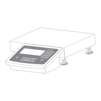
Illustration and identification of load cells and junction box on a weighing platform.
Open view of Junction Box 1, showing connections for load cells and the connecting cable.
Open view of Junction Box 2, showing connections for load cells and the connecting cable.
Wiring diagrams for load cells to Junction Box 2 and color coding for cables.
Step-by-step guide for adjusting the off-center load using the junction box.
Method for adjusting off-center load in 4-load cell platforms by soldering resistors.
Specifications for test weights used to set overload stops for steel weighing platforms.
Color assignments for load cell connections from different manufacturers like Sartorius, Combics, and TEDEA.
Procedure for determining resistance values for off-center load adjustment using a specific equation.
Example calculation for determining the required resistor value for off-center load adjustment.
List of available resistors in the E24 Series with their part numbers and values.
Table correlating adjustment resistor values with off-center load ranges for different test weights.
Graphical representation of adjustment resistor vs. off-center load for 350 Ohms initial resistance.
Graphical representation of adjustment resistor vs. off-center load for 1000 Ohms initial resistance.
Detailed service specifications including capacity, readability, and tolerances for MW/MAP-L models.
Detailed service specifications including capacity, readability, and tolerances for MW/MAP-LCE models.
Service specifications for MW/MAP-NCE models up to 60kg capacity.
Service specifications for MW/MAP-NCE models from 150kg up to 3000kg capacity.
Table listing error codes related to keys, program memory, and platform compatibility.
Table listing error codes related to scale functions, load limits, and data storage.
Table listing error codes for blocked functions, missing weighing platforms, and no connection.
Step-by-step guide to activate the service mode using the setup and code menu items.
Instructions on saving the service password and navigating within the service mode menus.
Procedure for configuring the A/D converter, including selecting standard or verifiable configurations.
Steps to save the A/D converter configuration and perform post-configuration adjustments.