3
Contents
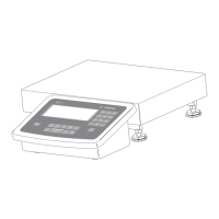
Repairing the Weighing Platforms
Replacing the Connecting Cable 29
Replacing Load Cells 30
Torque Values 31
Replacing the Load Cell Foot 32
Color Codes of the Wiring
for Weighing Platforms, Models MAPS 32
Wiring Diagram for the Load Cells (Junction Box 2) 32
Connections in the Junction Box
for the Load Cells 1-4 33
Connections in the Junction Box
for the A/D Converter 33
Service Specifications
Service Specifications MW...-L / MAP...-L 34
Service Specifications MW...-LCE / MAP...-LCE 35
Service Specifications MW...-NCE / MAP...-NCE 36
Service Specifications MW...-NCE / MAP...-NCE 37
Adjusting the Weighing Platform
Load Cell Connection (Color Assignments) 38
Determining the Resistance for Adjustment
of the Off-center Load 39
Determining Resistance Values 39
Sample Calculation Based on Diagram 2 40
Resistors Available in the E24 Series (+/- 5%): 41
Selecting the Adjustment Resistor 42
Adjusting Off-center Load with 1000 Ohms Initial
Resistance 42
Selecting the Adjustment Resistor: 43
Diagram 1 43
Adjusting Off-center Load with 350 Ohms
Initial Resistance 43
Diagram 2 44
Adjusting Off-center Load with 1000 Ohms
Initial Resistance 44
Error Codes
Err 101-343 ; InF 01-06 45
InF 07-73 46
InF 74-99 47
Description of the Equipment
Activating the Service Mode 48-49
Configuring the A/D Converter 50-51