CONTROL MODULES
Cont.
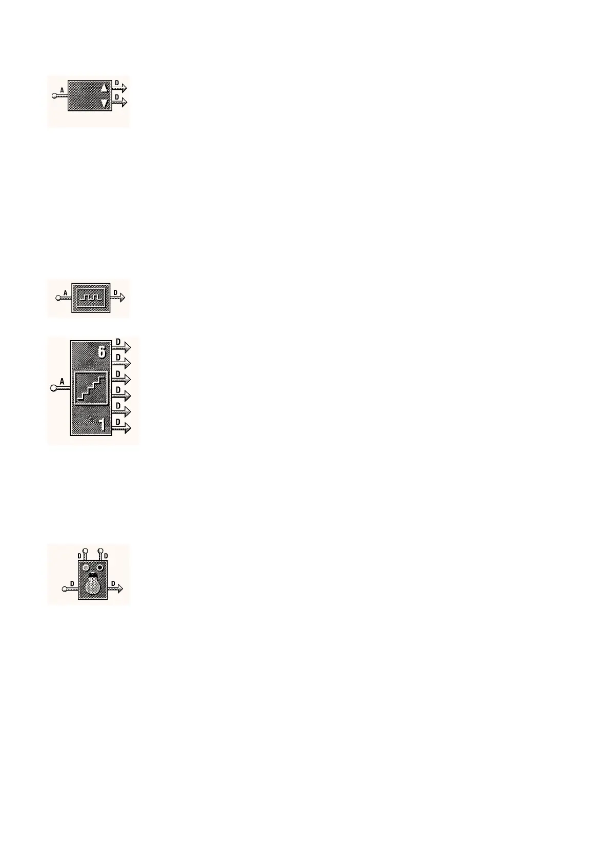
PULSED PAIR DRIVER MODULE
x 4
Stroke Time
This parameter allows the actuator stroke time to be set and is used b
the IAC to determine the position of the actuator on the output sta
e.
0 to 10,000
Seconds
65 Secs
Run On Time
This parameter sets the maximum actuator run on time. The output
will be turned off if the pulse pair driver has been runnin
in one
direction for lon
er than the pro
rammed Run On Time.
0 to 10,000
Seconds
600 Secs
Action
review onl
This parameter displa
s the current output state of the sta
e.
Stopped, Increasin
,
Decreasin
, at
Minimum or at
Maximum
–
Current Position
as a percenta
e of stroke
review onl
This parameter displa
s the approximate position of the actuator as a
percenta
e of its full stroke, where 0 = full
Closed and 100 = full
Open.
0 to 100% –
Current Run Time
review onl
This parameter displa
s the number of seconds that the actuator has
been runnin
in one direction. The number of seconds is reset to zero
when the direction of movement chan
es.
0 to 3,600
Seconds
–
PULSE WIDTH MODULATION MODULE
x 6
Cycle Period
The len
th of the c
cle period corresponds to the pulse time re
uired
for 100% openin
of the wax actuator. This parameter allows the c
cle
period to be set. The IAC then uses this time to work out the len
th of
pulse re
uired to position the actuator when it is bein
controlled.
1 to 10,000
Seconds
20 Secs
STEP DRIVER MODULE
x 4
When drivin
the step driver module from a volta
e or control module
sta
e output then values between 0 and 100 should be set where 0 =
0V or full
Off and 100 = 10V or full
On.
Step 1 Switch on Point (Bottom Step)
This parameter is used to set the switch on point for the step.
0 to 10,000 10
Step 2 Switch on Point
This parameter is used to set the switch on point for the step.
0 to 10,000 20
Step 3 Switch on Point
This parameter is used to set the switch on point for the step.
0 to 10,000 40
Step 4 Switch on Point
This parameter is used to set the switch on point for the step.
0 to 10,000 60
Step 5 Switch on Point
This parameter is used to set the switch on point for the step.
0 to 10,000 80
Step 6 Switch on Point (Top Step)
This parameter is used to set the switch on point for the step.
0 to 10,000 90
Switching Hysteresis
This allows the h
steresis to be set for all the sta
es and should
alwa
s be set to less than the smallest
ap between steps, this should
be done to avoid erratic control.
0 to 100 5
LIGHTING CONTROL MODULE
x 1
This module is used to switch the li
htin
on and off. The primar
input is normall
connected to the timeschedule On output
s
. The two
override inputs can be used to override the li
htin
On or Off. The
di
ital output is then used to switch the li
hts.
Status
review onl
This parameter displa
s the actual li
htin
output state.
Off or On –
DIP 1
The li
hts can be set up to dip off at a point before the
are set to
o
off. This parameter allows the point for the dip to occur to be set. Set
to 0 to disable the dip.
0 to 10,000
Seconds
0 Secs
DIP 2
A second dip is allowed as a final warnin
that the li
htin
is about to
be switched off. The point at which this dip occurs is set from this
parameter. Set to 0 to disable the dip.
0 to 10,000
Seconds
0 Secs
DIP Time
This sets the len
th of time that the li
hts dip off for.
0 to 10,000
Seconds
1 Sec
Computer Override
This parameter is used to override the li
htin
schedule from the
computer.
NOTE:-
The li
hts will not dip the
will be turned off immediatel
the
IAC receives the si
nal.
MODULES AND FUNCTIONS
Bubbleland
Symbol Module Range Default
DS 2.951A 10 - 24 05/98


 To Next Page