MODULES AND FUNCTIONS
Bubbleland
Symbol Module Range Default
LOGIC MODULES
Deviation
1 to 10,000 0
Time
1 to 10,000
Seconds
0 Secs
LOGIC MODULES
x 20, total number of an
combination of ‘NOT’,
‘AND’ and ‘XOR’ Gates
‘NOT’ Modules
This module re
uires no settin
and is used to reverse the di
ital
inputs i.e. On/Off inputs. This can be an
On or Off si
nal within the
IAC. For example, if a di
ital si
nal is Off when it
oes into the inverter
it will be transmitted out as On and vice versa. In con
unction with the
"AND"
ates, and ‘XOR’ Gates these inverters can perform interlock
functions.
‘AND’ Gate Modules
This module is used to take 2 di
ital inputs and "AND" them to
ether to
ive a new di
ital output. The
ate must have both di
ital si
nals as
On before it will
ive an On output. In con
unction with the ‘NOT’
ates
and ‘XOR’
ates these
ates can perform interlock functions.
XOR (EXCLUSIVE OR) Gates
XOR GATE, one input onl
must be On to
ive an On out. E.
. Off, On
= On out
NOTE:-
All di
ital inputs work as a normal OR Gate within normal
modules when multiple di
ital si
nals are applied to a sin
le di
ital
input. That is an
number of the inputs are On then the output is On.
E.
. Off, On, Off, On, On in = On out
B
placin
a NOT Gate after an AND Gate the output is inverted thus
providin
a NAND
ate e
uivalent. A ‘NOR’
ate is created b
connectin
two or more inputs into a ‘NOT’
ate. B
placin
a NOT
Gate after an XOR Gate an EQUIV Gate is created
if both inputs are
the same then the output is on if not the output is OFF
.
LATCH MODULES
x 8
The Latch module is used to take a momentar
Di
ital input and
ive a
latched output. The output will now sta
on until it is cleared b
the
reset input bein
set momentaril
to on.
This module is used to monitor a pulse t
pe si
nal and create a lon
er
si
nal.
DELAY MODULES
x 8
The Dela
module enables an incomin
di
ital si
nal to be
manipulated. B
dela
in
the on state
ou can ensure that the
incomin
si
nal must be on for a minimum amount of time before it is
reco
nised. B
dela
in
the off state of the incomin
si
nal a
minimum on time can be
uaranteed. The output from the module can
then be used as an output to another module.
Period
0 to 10,000 Seconds 0 Secs
Hold On/Off
On or Off On
Rising Edge/Falling Edge
Risin
or Fallin
Fallin
Re-trigger
Yes or No No
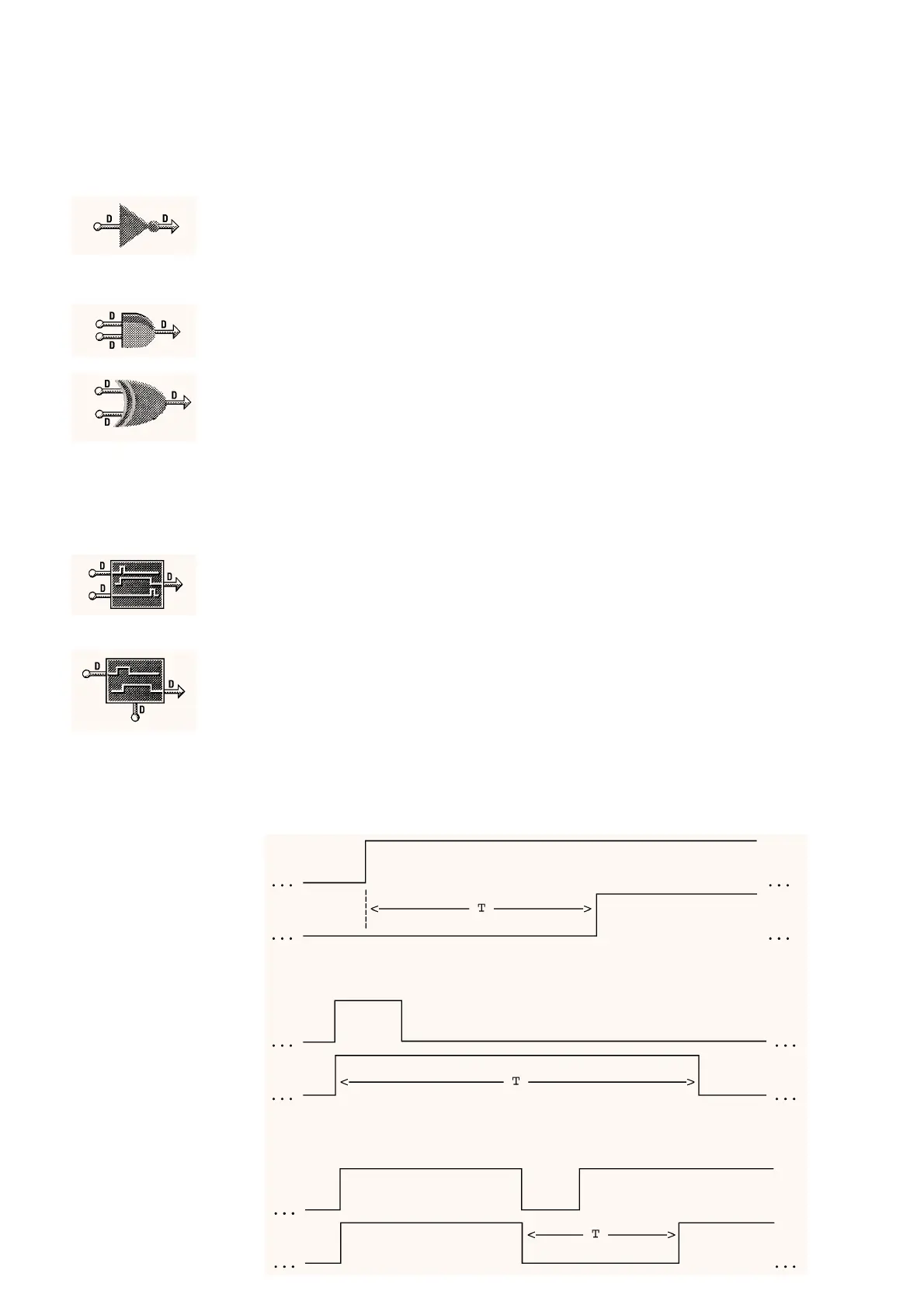
Input
Output
Input
Output
Input
Output
Example 1: Start Up Delay:
Period = T
Dela
T
pe = Hold Off
Ed
e = Risin
Re-tri
er = No
Example 2: Minimum Run Time:
Period = T
Dela
T
pe = Hold On
Ed
e = Risin
Re-tri
er = No
Example 3: Minimum Off Time:
Period = T
Dela
T
pe = Hold Off
Ed
e = Fallin
Re-tri
er = No
05/98 5 - 24 DS 2.951A