GENERAL NOTES
1. The IAC uses two t
pes of si
nal internall
. The
are as follows:-
Analo
ue Values from –10,000 to +10,000 these represent temperature
°
C,
°
F
, Volta
es, Ohms, Lux and control outputs.
Di
ital si
nals, these si
nals are either On or Off.
2. Analo
ue inputs or outputs cannot be directl
connected to Di
ital inputs or outputs. To convert an analo
ue value to a di
ital si
nal use a
threshold module.
3. When handlin
Volta
e or controller output si
nals
ou should note that values are in the ran
e of 0 to 100 where 0 = Off or 0 Volts and
100 = full On or 10 Volts.
4.
°
C,
°
F, Ohms and Lux are all displa
ed as actual values e.
. 20
°
C = 20, 68
°
F = 68, 2000 Ohms = 2000 etc.
5. When usin
a controller module for sin
le sta
e onl
the unused sta
e should be set as follows:-
Proportional Band
= 10,000
Integral Action Time
= 0
Derivative Action Time
= 0
Ramp Time
= 0
6. Maximum of 100 links between modules per IAC base unit.
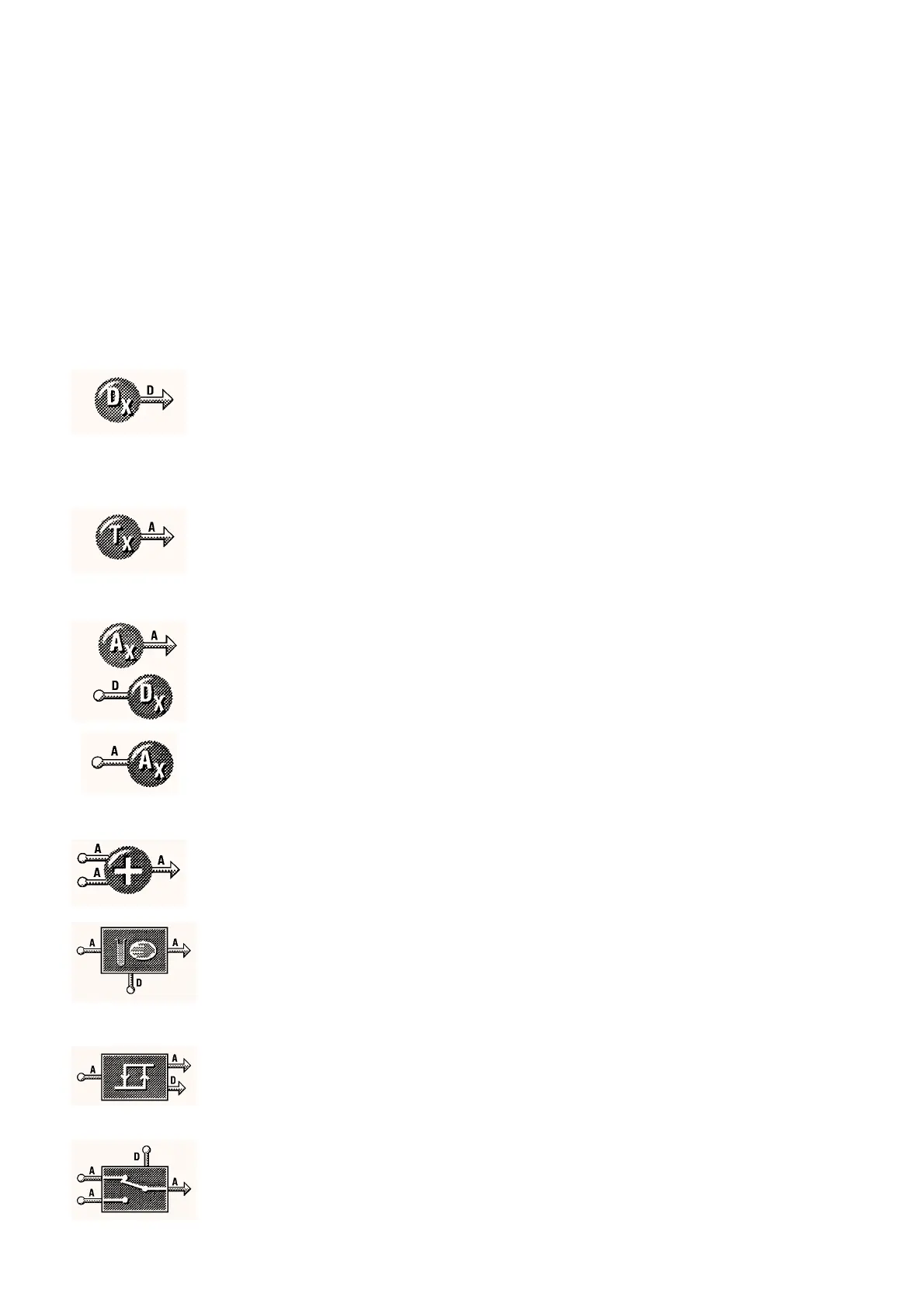
MODULES AND FUNCTIONS
Bubbleland
Symbol Module Range Default
INPUT/OUTPUT MODULES
DIGITAL INPUT MODULE
x 8
Current State of Input
review onl
This parameter displa
s the current input state.
On or Off –
Latch Input
This parameter allows the di
ital input to be latched so that a
momentar
input will switch the module on and a second input will
switch it off.
Yes or No No
Toggle
This parameter switches a latched input into the opposite state.
On or Off –
TEMPERATURE (RESISTIVE) INPUT MODULES
x 6
Current Measured Value
review onl
This parameter displa
s the current input value in the selected units.
–40 to 150
°
C
–40 to 302
°
F
250 to 9750
Ω
0 to 10,000 Lux
–
Units Selection
This parameter selects the units that can be used for the input.
°
C,
°
F, Ohms or Lux
°
C
ANALOGUE INPUT MODULES (VOLTAGE)
x 6
Current Measured Value
as a percenta
e of 10 Volts
review onl
0 to 100% –
DIGITAL (TRIAC) OUTPUT MODULES
x 8
Output State
review onl
On or Off –
Override State
None, On or Off None
ANALOGUE OUTPUT MODULES
x 4
Current Output Value
as a percenta
e of 10 Volts
review onl
0 to 100% –
Override Value
e.
. 0 = 0V, 50 = 5V, 100 = 10V
0 to 100% 0%
Enable Override
On or Off Off
MATHS MODULES
SUBTRACTION, MULTIPLICATION, DIVISION AND
ADDITION MODULES
x 8, total number of an
combination
These modules allow mathematical operations to be carried out on
values within the controller. Each module can accept two value inputs
and the module will produce a value output. The addition module is
shown, left.
SAMPLE AND HOLD MODULE
x 6
This module is used to sample an Analo
ue value when the Di
ital
input on the module is momentaril
switched on. The sample module
will then output the current sample value. The module will keep the
value until the next time the Di
ital input is set to on, at which point
another sample is taken.
NOTE:-
If the Di
ital input is left set at on, the output of the module will
follow the module input.
HYSTERESIS MODULE
x 8
This module is used to pass on a chan
e in value onl
when that
chan
e is
reater than the value set in the module. When a chan
e is
passed throu
h the di
ital output is switched on briefl
. This can be
used to drive the Lo
in
module for event based lo
in
.
Hysteresis
0 to 10,000 1
ANALOGUE SWITCH MODULE
x 6
This module switches an analo
ue output between two analo
ue
inputs. The switchin
is tri
ered b
a di
ital input state. Possible
applications are sensor selection, override of fan speeds/actuator
position etc.
05/98 3 - 24 DS 2.951A