2 AGATE SATEL
terminal is disconnected from the common ground. You can connect to the LED terminal an
OC type control panel output programmed e.g. as the SERVICE MODE STATUS, BI SWITCH or
ZONE TEST STATUS.
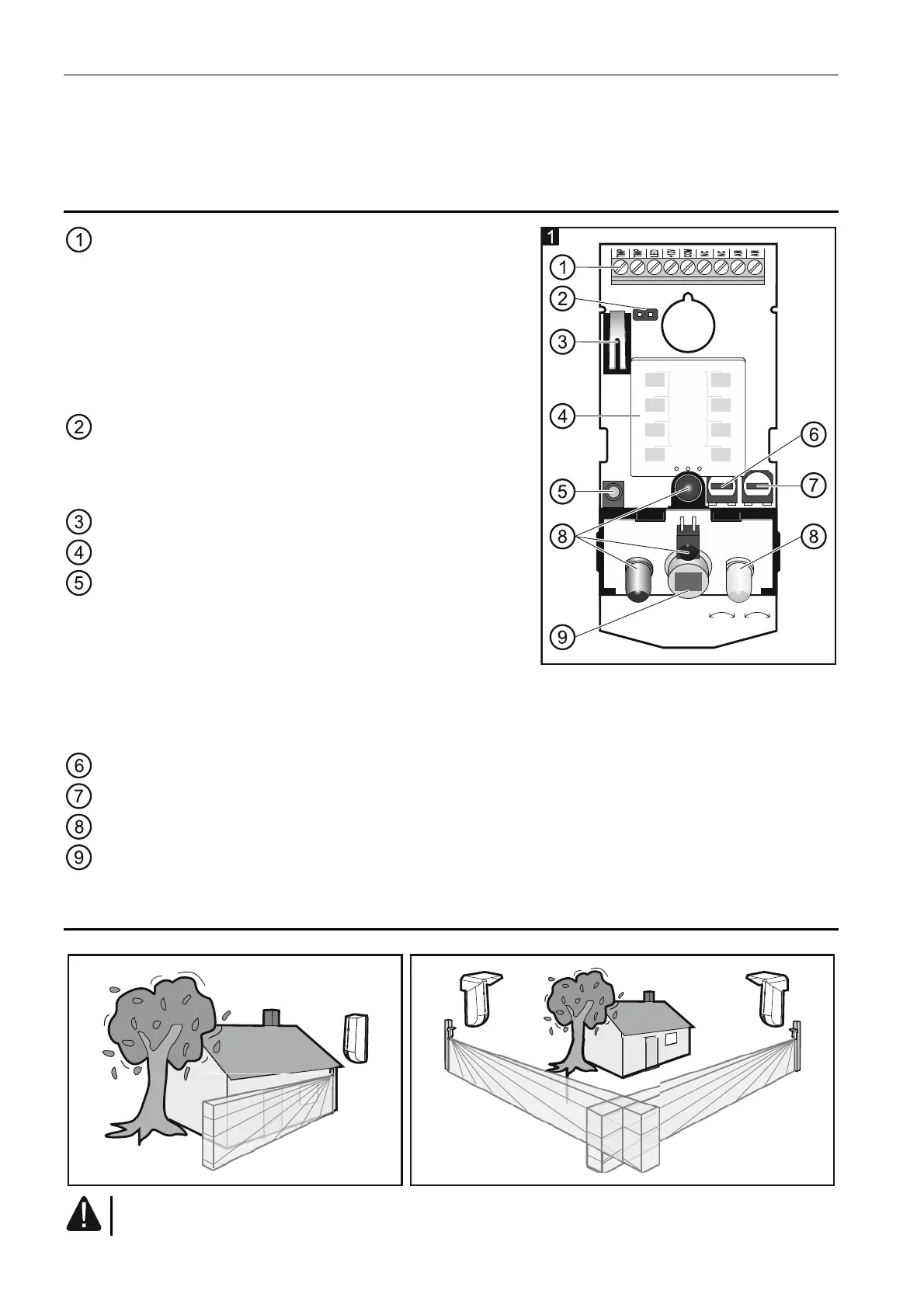
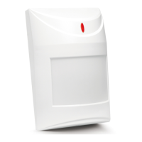
3. Electronics board
terminals:
uW-+- +PIR
TMP - tamper output (NC).
LED - remote LED control.
+12V - power input.
COM - common ground.
NC - alarm output (NC relay).
AM - anti-masking output (NC relay).
pins to enable/disable the LED indicators. If the
LED indicators are to be enabled, place the
jumper on pins (the remote LEDs enable/disable is
not available then).
tamper contact activated by cover removal.
microwave sensor.
tricolor LED to indicate:
– alarm – the LED lights red for 2 seconds.
– motion detection by the microwave sensor - the
LED lights green for 4 seconds.
– motion detection by the PIR sensor – the LED lights blue for 4 seconds.
– trouble – the LED lights red throughout the duration of trouble.
– warm-up – flashing alternately red, green and blue for about 45 seconds.
potentiometer for adjustment of the microwave sensor sensitivity.
potentiometer for adjustment of PIR sensor sensitivity.
anti-mask circuit LEDs.
dual element pyrosensor. Do not touch the pyroelectric sensor, so as not to soil it.
4. Installation
Disconnect power before making any electrical connections.