4 AGATE SATEL
4. Run the cable through the hole you made, and then strip insulation from the cable so that
it should extend a few millimeters beyond the material sealing the hole (Fig. 5). If the
detector is to be installed on the angle bracket included in the delivery set, make a hole in
the bracket and run the cable through it as shown in Fig. 6 (the detector can also be
mounted on the adjustable brackets, BRACKET A and BRACKET B, offered by SATEL).
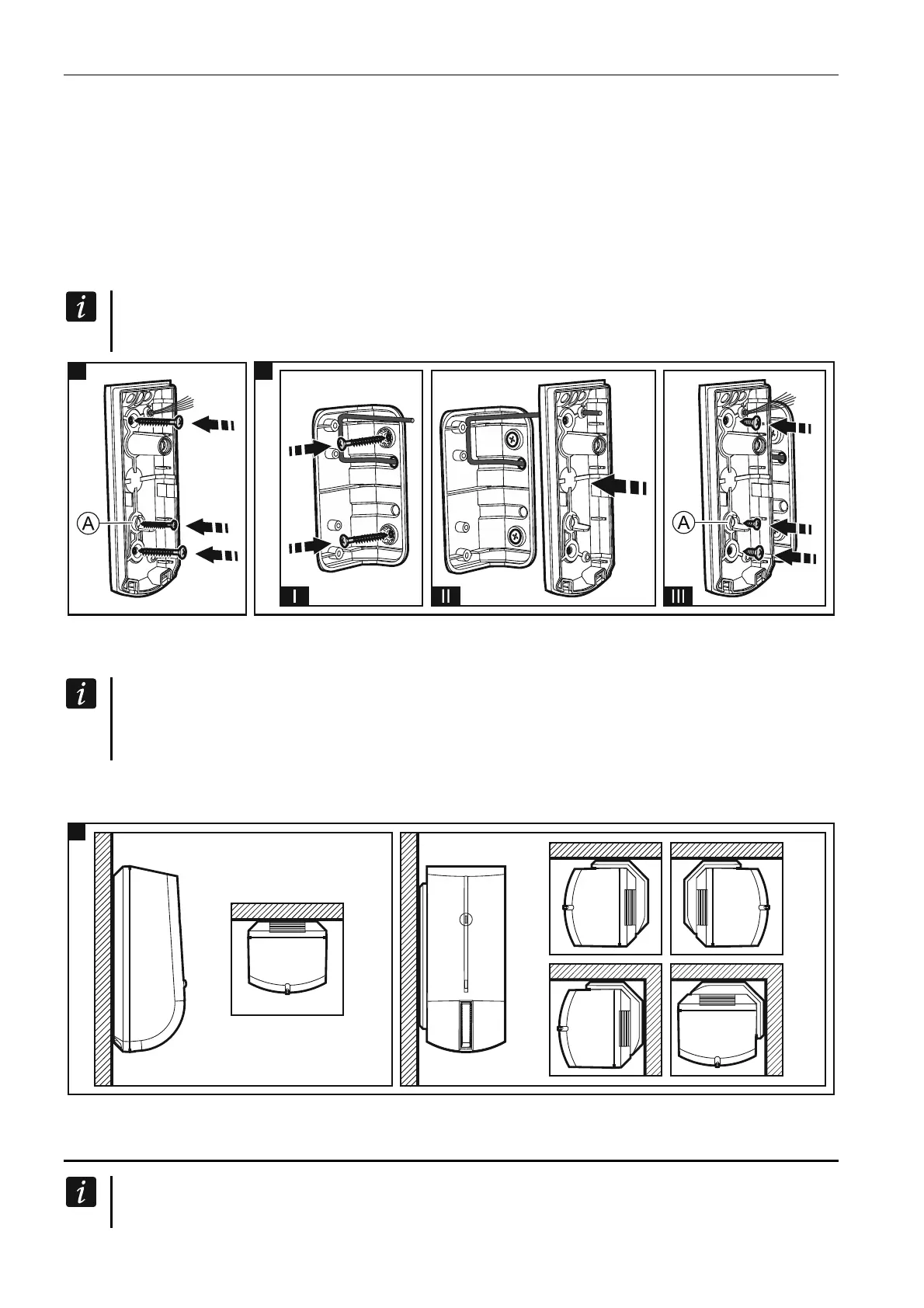
5. Mount the enclosure base directly to the wall (Fig. 5) or to the angle bracket screwed
down to the wall (Fig. 6). Wall plugs and screws are delivered with the detector. For the
hole designated by letter A on the figures 5 & 6, use the smaller screw. Fig. 7 shows the
possible ways of detector installation.
If the detector is to meet the requirements of EN50131 standard for Grade 3, it must
not be mounted on any bracket.
5 6
6. Fasten the electronics board.
7. Connect the wires to the corresponding terminals.
If the detector is to be installed outdoors, do not connect the anti-masking outputs to
the control panel zones. Severe weather conditions, including rain, fog or frost, can be
interpreted by the anti-mask circuit as an attempt to mask the detector.
8. Using potentiometers and jumper, set the detector working parameters.
9. Replace the cover.
5. Start-up and walk test
When starting the detector, its enclosure must be closed for the anti-mask feature to
work properly. After power-up, the detector is analyzing the environment in which it