Saia-Burgess Controls AG
User Manual Standby System │ Document 27-645 │ Edition ENG 02 │ 2017-04-26
Diagnostic Flags | Diagnostic Registers
Technical Imformation
3-3
3
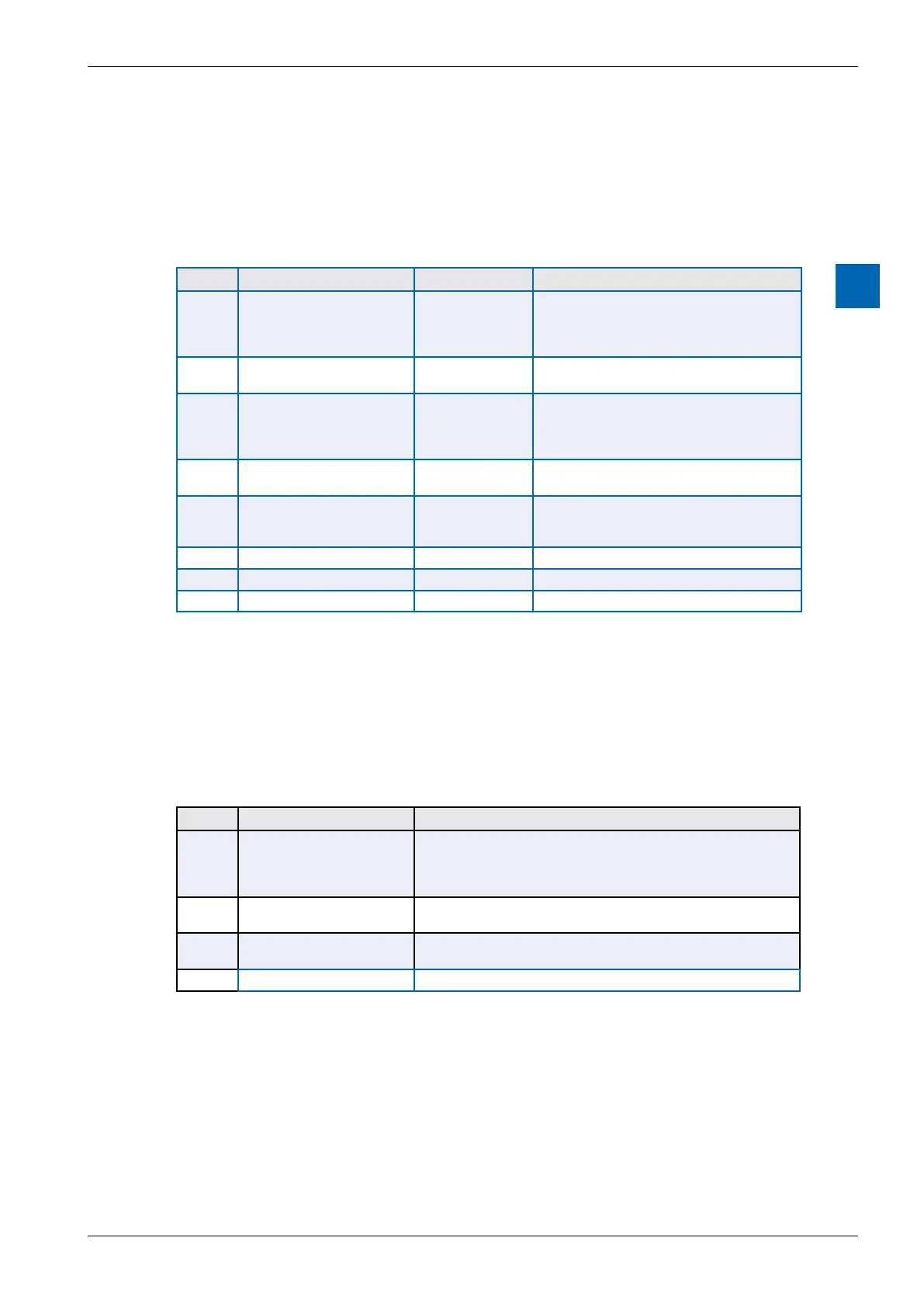
3.3 Diagnostic Flags
assigned, which are shown on the “System” tab of the Symbol Editor.
S.STANDBY.DiagFlagBase
Oset System Symbol Name Values Remarks
0 S.STANDBY.
PrimaryOrSecondary
0 = PRIMARY
1 = SECONDARY
-
gram is running on the Primary or the Second-
generated or executed in CPU1.
1 S.STANDBY.
StandbyOrActive
0 = STANDBY
1 = ACTIVE
or standby.
2 S.STANDBY.Redundacy 0 = NO
REDUNDANCY
1 = REDUN-
DANCY
1 = Data sync is working, both CPU1s have
the same program, standby switching can oc-
cur. If 0 then standby control is not available.
3 S.STANDBY.DataSyncOK 0 = FAILED
1 = OK
0 = Sync communications between the two
CPU1s has failed, 1 = it’s working
4 S.STANDBY.ProgSyncOK 0 = FAILED /
1 = OK / Same
sync cannot occur,
1 = programs are the same
5
-
Reserved
6
-
Reserved
7
-
Reserved
3.4 Diagnostic Registers
An array of 4 Registers is used for diagnostics on both CPUs. System symbols are
assigned, which are shown on the “System” tab of the Symbol Editor.
The base register symbol name is: S.STANDBY.DiagRegBase
Oset System Symbol Name Values
0 S.STANDBY.Status 1: IDLE
2: STANDBY
3: ACTIVE - Redundancy
4: ACTIVE - Non Redundancy
1 S.STANDBY.DataUpdate-
Time
The number of milliseconds between sync data updates
2 S.STANDBY.DataSendTime The time in milliseconds for the sync data to be transferred (tel-
egram time)
3
-
Reserved