Saia-Burgess Controls AG
User Manual Standby System │ Document 27-645 │ Edition ENG 02 │ 2017-04-26
Terminology
Standby System Overview
1-4
1
Redundant control solutions are created using two PCD3.M6880 Standby
Controllers. The input/outputs (process signals) are connected and controlled
via PCD3.T668 Ethernet smart RIOs. The RIO stations are connected to both
controllers via an Ethernet connection. This means there is no need to have
duplicate inputs, outputs, sensors and actuators. The two PCDs (primary and
secondary) monitor each other. If the active PCD fails, the standby PCD takes
over processing and control of the connected RIO stations. The process image
(I/O) and the internal PCD media (F, R, T, C, DB) - the synchronization data - are
continuously transferred from the active PCD to the standby PCD via the Ethernet
connection. This ensures uninterrupted switching from the active to the standby
PCD.
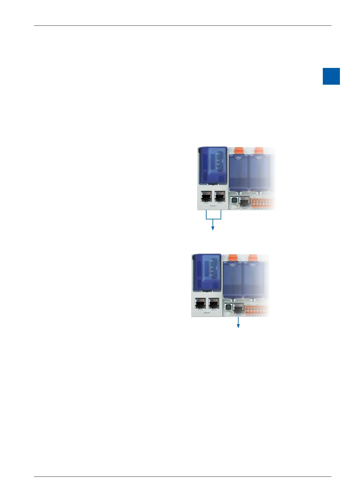
The Redundant CPU1 has two inde-
pendent Ethernet interfaces. The ETH
2.× interface is reserved exclusively for
operating the PCD3.T668 RIO stations.
The PCDs also synchronize their pro-
cess data via the same interface. For
security reasons, we recommend set-
ting up this network as a ring structure
third-party providers. We have had good
experiences with the industrial Ethernet
switches from Hirschmann.
Ethernet 2
(2 port switch)
The ETH 1 interface on CPU0 is avail-
able for connecting and operating other
systems and devices. For example,
SCADA systems can be connected via
this interface. SBC does not provide its
own SCADA system for redundant auto-
mation solutions, but almost any system
can be used. A single SCADA system,
or an additional redundant SCADA
system can be used if it supports re-
dundant controllers. The PCD3. M6880
controllers provide detailed status and
diagnostic information which can be
evaluated by the SCADA systems.
Ethernet 1