SBE SB-36 OPERATION MANUAL
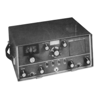
11 Meter Switching The "METER" switch is used to select the desired parameter
to be measured. The three functions of the switch are as
follows;
ALC: When transmitting, place the meter switch in the
ALC position. This will help in determining the
proper levels of microphone gain and ALC.
IP: In this position, the meter will indicate plate current
in the final amplifier tubes.
RF: In this position, the meter will indicate the relative
RF output power of the transceiver.
"S” Meter: When receiving, the front panel meter indicates
the signal strength of the incoming receive signal
irregardless of the position of the meter switch.
12 Plate control The Plate Tuning Capacitor resonates the final amplifier Pi-
network capacity by varying the input capacity of the Pi-
network.
13 Load control The Load Control matches the output impedance of the Pi-
network
to the impedance of the load.
14 PHONES Connector The jack connector that permits low impedance head- phone
connection. When the head-phone plug is inserted, the
speaker is disconnected from the circuit.
15 MIC connector The jack connector that permits a low-medium impedance
microphone audio output and push-to-talk lines to be
connected to the transceiver.
16 Mode Switch P. OFF: Main power removed from the transceiver.
TUNE: Tune position is used for transmitter tune-up (USB
selected).
USB: For upper sideband operation.
LSB: For lower sideband operation
CW: For CW operation.
17 "RF" Gain control A potentiometer which varies the operating bias of the first
receiver RF amplifier.
18 "AF" Gain Control The potentiometer which is used to set the speaker or
headphone audio output to a comfortable listening level.
19 VFO Tuning Knob A control that permits tuning of the VFO. Its movement
covers a 500 kHz band spread range with approximately
30 kHz per revolution. The exact position in the band, to
within +100 Hertz is indicated in the Nixie-tube
display.
NoobowSystems Lab. Tomioka, Japan 2003 http://www.noobowsystems.com/ Page 14 / 56