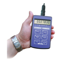
The IPM25 is a portable, microprocessor-based instrument designed for use as a strain gauge or load cell handheld display. It interfaces with any full bridge sensor with an output sensitivity of up to 50mV/V, and can be used with bridge resistances from 85Ω upwards. The device is powered by two internal non-rechargeable AA alkaline batteries.
Function Description:
The primary function of the IPM25 is to provide a digital readout for strain gauge and load cell sensors. It supports two independent ranges, allowing for flexible application. The device can display instantaneous, peak, or trough values, and offers a display hold/freeze function. It also supports gross/net indication, shunt calibration checks, and can be configured and calibrated using its front panel push buttons. A key feature is its compatibility with TEDS (Transducer Electronic Data Sheet) sensors, which enables "Plug and Play" functionality, simplifying sensor configuration and improving efficiency by eliminating manual data entry and providing detailed calibration information electronically.
Important Technical Specifications:
- Input Type: Strain Gauge Full Bridge Sensors
- Input Range: Up to ±5mV/V (±50mV/V option available with factory set option)
- Non Linearity: ±0.005% FSD
- Thermal Drift: <25 ppm/°C
- Excitation Voltage: 5Vdc (±4%), 59mA maximum current
- Minimum Bridge Resistance: 85Ω (four 350Ω sensors in parallel)
- Internal Battery: 2x AA size alkaline, accessible via sealed rear compartment
- Battery Life: 45 hours (Typical 450 hours in low power mode with a 350Ω sensor)
- Update Rate: Up to 40mS (configurable in menu)
- Display Type: 7-digit LCD display, 8.8mm high digits
- Display Resolution: 1 part in 250,000 at 1Hz update rate; 1 part in 65,000 at 10Hz update rate
- Electrical Connection: 5-pin Binder socket (mating plug supplied)
- Physical Size: 152mm (H) x 90mm (W) x 34mm (D)
- Weight: 260 grams
- Operating Temperature: -10°C to +50°C
- Environmental Rating: IP65 (when mating plug fitted)
- Enclosure Type: ABS, dark grey (Leather Carry Case Optional)
- European EMC Directive: 2004/108/EC, BS EN 61326-1:2006, BS EN 61326-2-3:2006
- RS232 Output (option): 9600 baud, 1 stop bit, no parity, 8 data bits (ASCII format)
Usage Features:
- Switching On/Off: Press and hold the power button for 3 seconds. An auto-off feature can be configured in the menu to automatically power off the device after a preset time of inactivity, conserving battery life.
- RANGE Button: Toggles between two independent scales. An LED indicates the selected range. If TEDS is enabled, only one range is permissible.
- HOLD Button: Freezes the current display value. Pressing it again releases the display. The HOLD LED illuminates, and the display flashes to indicate hold mode. This feature is not available in peak or trough hold modes.
- GROSS/NET Button: Toggles between gross and net display values. Net mode allows for zeroing the display to show changes from a specific measurement point, useful for tare weight applications.
- SHUNT CAL Button: When pressed and held, it shunts a 100kΩ resistor across the negative excitation and negative signal connections, generating a simulated output. This allows for checking calibration accuracy or connection integrity. The SHUNT CAL LED illuminates, and the display flashes.
- PEAK Button: Displays the highest reading reached. To reset, press PEAK and TROUGH simultaneously. The PEAK LED illuminates, and the display flashes. Peak capture rate is up to 25Hz. Press PEAK again to exit peak mode.
- TROUGH Button: Displays the lowest reading reached. To reset, press TROUGH and PEAK simultaneously. The TROUGH LED illuminates, and the display flashes. Trough capture rate is up to 25Hz. Press TROUGH again to exit trough mode.
- Configuration Menu: Accessed by pressing and holding RANGE and GROSS/NET buttons for 3 seconds. Allows tailoring operation for specific applications, with settings independent for each range.
- SET ZERO: Introduces a fixed offset to the display value, allowing gross and net values to be displayed with this offset accounted for. Can also be set by pressing GROSS/NET and HOLD simultaneously.
- SET RATE: Sets the display update rate (25Hz, 10Hz, 3Hz, 1Hz, 0.5Hz). 25Hz is only available in PEAK or TROUGH mode.
- SET OVER: Sets a visual overload alarm. The word "OVERLOAD" appears on the screen when the set value is reached.
- SET OPER (Power Save Mode): Enables or disables a power save mode that updates at 1 update per second and pulses sensor excitation, increasing battery life significantly (from 45 to 450 hours with a 350Ω sensor). Accuracy is reduced to 1 digit in 10,000 in this mode.
- AUTO OFF: Sets an auto power-off time in minutes (05 to 99). "00" disables auto-off.
- RS232 (option): Enables or disables the RS232 output.
- Calibration Menu: Accessed by pressing and holding RANGE and HOLD buttons for 5 seconds. Used to calibrate each of the two ranges and set display resolution.
- SENS 5.0/50.0: Changes the sensor input sensitivity range (factory set to 5mV/V, can be changed to 50mV/V by moving an internal link LK1 to JP1).
- SET RES: Sets the decimal point position and display resolution.
- CALIBRATE: Enters the calibration routine (disabled when TEDS is enabled).
- LIVE Calibration: Reads sensor signals at two calibration points to automatically scale the IPM25. Requires applying known loads to the sensor.
- TABLE Calibration: Uses the sensor's sensitivity figure (in mV/V) from its calibration certificate to scale the IPM25.
- CAL VAL: Allows viewing offset and gain figures from stored calibrations for maintenance or transfer.
- Millivolt per Volt Calibration Menu: Accessed by pressing and holding RANGE and PEAK buttons for 10 seconds.
- 5.0 gAin/50.0 gAin: Changes the factory gain calibration to a measured value for 5mV/V or 50mV/V ranges.
- 5.0 OFFS/50.0 OFFS: Changes the factory offset value to a measured value for 5mV/V or 50mV/V ranges.
Maintenance Features:
- Internal Connections: The manual provides a diagram of internal connections, useful for tasks such as changing internal shunt calibration resistors or re-inserting range legends.
- Battery Replacement: The device uses two AA alkaline batteries, accessible via a sealed rear compartment.
- TEDS (Transducer Electronic Data Sheet): When enabled, TEDS automatically calibrates the IPM25 using data from the TEDS chip on the sensor, eliminating manual calibration. TEDS limitations include requiring DS2431 or DS2433 devices and template 33, with specific restrictions on physical values, precision, electrical values, bridge type, and excitation range.
- Calibration Procedures: Detailed instructions are provided for both LIVE and TABLE calibration methods, including steps for applying low and high stimuli, entering display values, and confirming settings. The manual also outlines a millivolt per volt calibration procedure for precise adjustments of gain and offset.
- Error Handling: The device indicates "FaiLEd" if calibration is unsuccessful, prompting the user to repeat the procedure and check sensor connections.
- Unit Labels: Engineering unit legends can be slid into a window on the inside of the front panel to identify the units being displayed for each range.