SCARAB M6 SWEEPER KIT
25 Operator’s Manual Amdt.1 - 03 November 2009
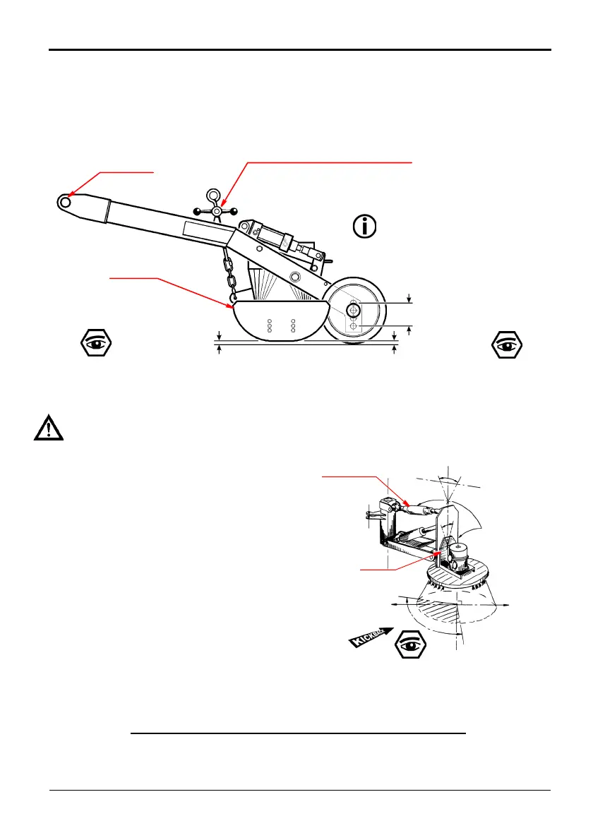
SUCTION NOZZLE CLEARANCES
Inspect the suction nozzle flaps to verify that they are in good condition
and do not show excessive wear. Adjust as necessary to achieve the
correct flap to ground clearances (Refer to Fig. 11).
Fig. 11 Suction Nozzle Clearance - Factory Set-up
FRONT FLAP = 20 mm
REAR FLAP = 30 mm
SIDE FLAP = 20 mm
Adjust FOR
Parallel Running
NOZZLE MINIMUM-HEIGHT ADJUSTER
Adjust For
Parallel Running
TOWPOINT
SKID PLATE
The height adjuster chain has been
superseded by a stainless steel lanyard
on later machines.
Side Flap is located at
opposite end of suction
nozzle from
NOTE:
These clearances are based on the
factory set-up. For some operating
conditions, it might be found that,
alternative clearances are preferred
SIDE BRUSHES & SKIRTS
DO NOT ATTEMPT TO ALTER THE BRUSH SETTINGS WHILE THE BRUSH IS ROTATING.
Fig. 12 Brush Tilt Adjustment
TO FRONT
1
2
0
°
AREA IN CONTACT
WITH THE ROAD
BRUSH
ADJUSTMENT
POINTS
TOP LINK
MOTOR
PLATE
KI
C
K
B
A
C
K
An effective brush set-up ensures good
sweeping performance. The following
se
ttings produce excellent results in
most conditions. Experience will
determine if other settings are better
suited to specific conditions.
1. The brush s
hould be angled so
that it sweeps with its outer
leading edge. About 33% (120°)
of its circumference should be in
contact with the road surface.
2. The ski
rt adjacent to the brush,
which positions material for the
suction nozzle, should also be in
good condition and set so that
it just clears the ground.