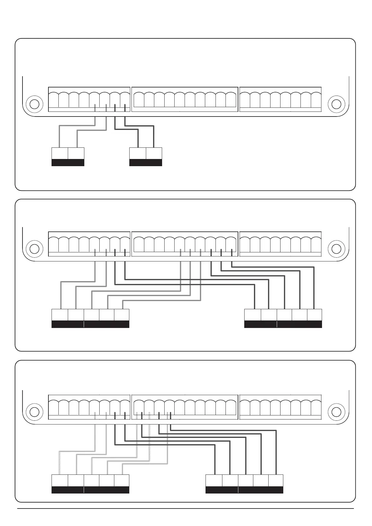
2.1 PC190 Motor Wire Connections
2. Wire Connections and System Learning
Standard Motor Connection
M1+ M1- M2+ M2-
Lit+ Lit- Lat+ Lat-
5V S1 S2 GND Lmt1 Lmt2 GND Lmt3 Lmt4 GND
DKey SKey GND Ph1 PhVcc GND Ph2 PhVcc
PC190-PCB1
40121-377-A1
RF1
K5
K3
K2K1
CO
NC NO
+-- +
NONC
- +
NONCNC NO
+-
1 2 3 4 5 6 7 8
9 10 11 12 13 14 15 16 17 18
19 20 21 22 23 24 25 26
Lmt3 Lmt4
Lmt2
SKey Lit+ Lit- Lat+ Lat- M1+ M1- M2+ M2- Ph1 PhVcc Ph2 PhVcc
S1 S2
5V
GND
GND
GND DKey
GND Lmt1
GND
PC190-PCB1
40121-377-A1
+ -
T4
SW3
UP
J1
Q17
R113
R112
R111
R110
R108
R107
R106
R105
R104
R103
R102
SW1
RF-LEARN
RF1
MOV1
K5
K3
K2K1
J7
J2
F1
DB1
SW4
SET
SW5
DOWN
NC NO
CO
+-
NC NO
CO
+-- +
CO
NONC
- +
CO
NONC
NC NO
CO
+-
-
+
1 2 3 4 5 6 7 8
9 10 11 12 13 14 15 16 17 18
19 20 21 22 23 24 25 26
-
+
-
+
Motor1 Power
-
+
Red White Black
Motor2 Power
Motor1 Power Hall sensor
-
+
Black
Motor2 Power Hall sensor
Lmt3 Lmt4
Lmt2
SKey Lit+ Lit- Lat+ Lat- M1+ M1- M2+ M2- Ph1 PhVcc Ph2 PhVcc
5V S1 S2
DKey GND
GND
GND
GND Lmt1
GND
PC190-PCB1
40121-377-A1
+ -
T4
SW3
UP
J1
Q17
R113
R112
R111
R110
R108
R107
R106
R105
R104
R103
R102
SW1
RF-LEARN
RF1
MOV1
K5
K3
K2K1
J7
J2
F1
DB1
SW4
SET
SW5
DOWN
NC NO
CO
+-
NC NO
CO
+-- +
CO
NONC
- +
CO
NONC
NC NO
CO
+-
-
+
1 2 3 4 5 6 7 8
9 10 11 12 13 14 15 16 17 18
19 20 21 22 23 24 25 26
-
+
Green Blue Black
Motor1 Power Limit Switch
-
+
Green Blue Black
Motor2 Power Limit Switch
Red White
Motor with mechanical limit switch (not included)
Motor with hall sensor (not included)
 Loading...