A
B
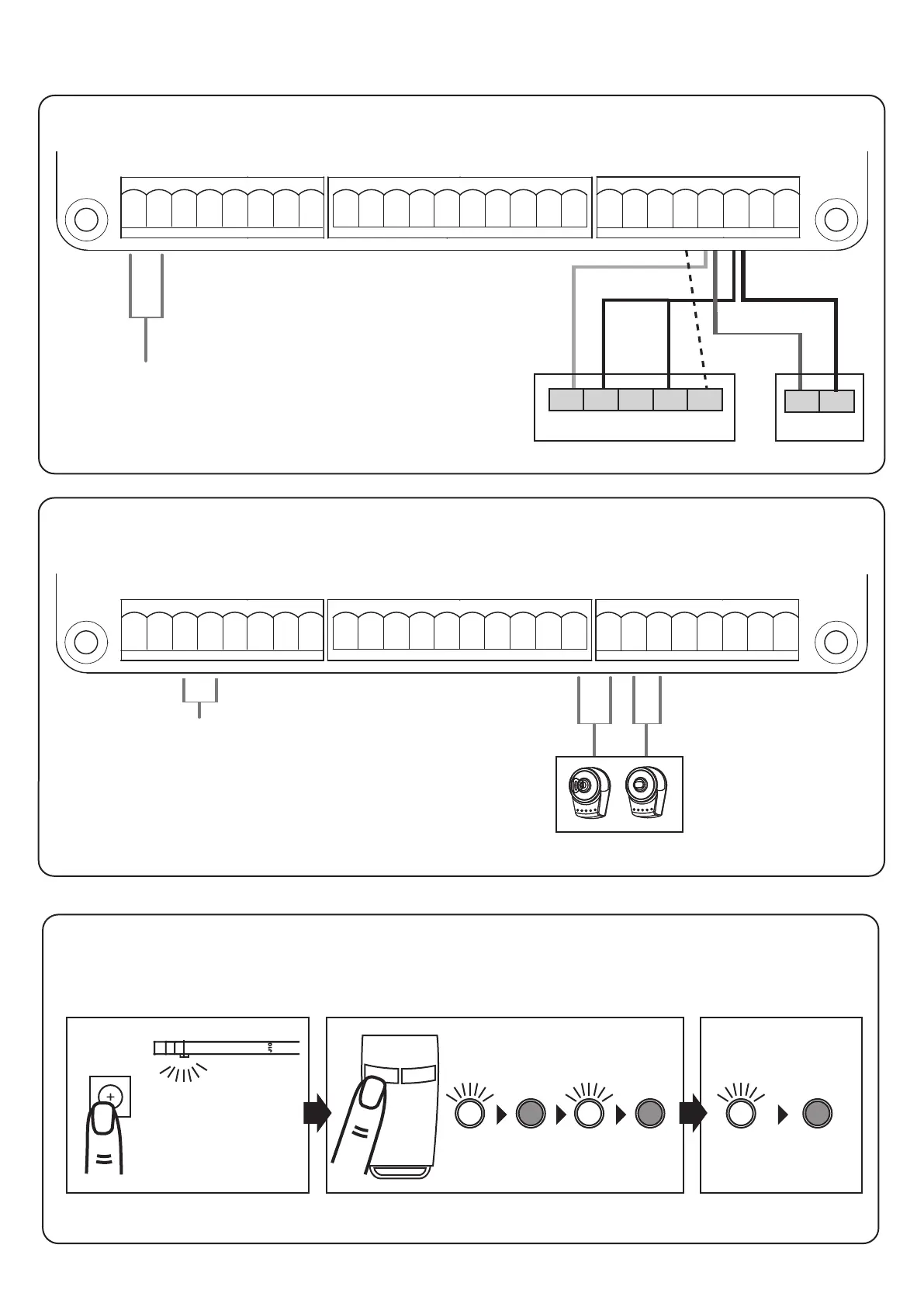
2.3 Coding in a Remote Control
Press “RF-learn” button for 2 seconds, the blue LED will come on; then press the (A) button on the remote;
the Blue LED will blink three times and then turn off after 10 seconds. The remote is now coded in.
Blue LED blinks three times
Blue LED OFF
Blue LED ON
2 Sec
RF-Learn
NOTE: Erase transmitter Memory (on motherboard): Press and hold the “RF-LEARN” button on the circuit board for 10 seconds
until blue LED goes out.
Lit+ Lit- Lat+ Lat- M1+ M1- M2+ M2-
5V S1 S2 GND Lmt1 Lmt2 GND Lmt3 Lmt4 GND
3 21 5 6 8 7 4
9 10 16 15 14 13 12 11 1817
2.2 Accessories connections
Connections photocell & signal light (SL only available in the SL set)
3 21 4 7 65 8
9 10 16 15 14 13 1812 11 17
21 20 19 25 24 2623 22
Connection for
dual gate
operation
Connection for
single gate
operation
Connections for push-button / key-switch / electric lock (not included)
NOTE: Operating
under the "FK /
options can be changed
FL" setting (see p. 30).
DC+ GND
TX
N.O. N.C. COM
RX
DKey SKey GND Ph1 PhVcc GND Ph2 PhVcc
19 20 21 22 23 24 25 26
DC+ GND
Photocell
Signal light with
24 V AC/DC
connection
Electric Lock AC/
DC Connection
Lit+ Lit- Lat+ Lat- M1+ M1- M2+ M2-
5V S1 S2 GND Lmt1 Lmt2 GND Lmt3 Lmt4 GND
DKey SKey GND Ph1 PhVcc GND Ph2 PhVcc
WARNING: The electric lock must be mounted on
the gate that opens first and closes last!