EasyManua.ls Logo

Schartec P190 Control Box User Manual

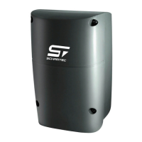
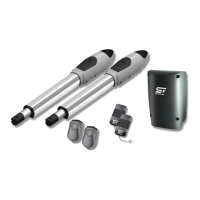
Schartec P190 Control Box
34 pages
Go to English
To Next Page IconTo Next Page
Page #1 background imageLoading...
Page #1 background image
P190 Steuerung
24V DC
Getriebe
MOTOR
Drehtorantrieb
für den Privatbereich
Anleitung
English instructions begin on page 18

Questions and Answers:

Schartec P190 Control Box Specifications

General IconGeneral
ModelP190
CategoryGate Opener Control Box
Power Supply230V AC
Motor Voltage24V DC
Max. Motor Power190W
Protection ClassIP54
Weight1.5 kg
Safety InputYes
Operating Modespedestrian mode
Operating Temperature-20°C to +50°C

Summary

Important Safety Information

Safety Instructions for Gate Operation

Defines intended use, gate limits, and operational restrictions for the swing gate operator.

Product Warranty Details

Outlines warranty coverage, duration, and conditions for the product, including exclusions.

Installation Preparation and Safety

Gate System Pre-Installation Checks

Ensures the gate is operational and safe before proceeding with operator installation.

Safe Installation Practices

Emphasizes compliance with regulations, lock removal, and protection during drilling.

Safety Warnings and Notices

Provides critical safety advice regarding control devices, children, and warning signs.

Inspection and Maintenance

Regular Inspection and Maintenance

Recommends expert inspection and user optical tests for safety and proper function.

Control Box Diagram

PC190 Control Box Overview

Illustrates the internal components and connection points of the control box.

Motor Wiring and System Setup

PC190 Motor Wire Connections

Details wiring for standard, mechanical limit switch, and hall sensor motor types.

Accessories and Remote Control

Accessory Connection Guide

Explains wiring for photocells, signal lights, and access control devices.

Remote Control Pairing Procedure

Describes the step-by-step process for pairing a remote control with the system.

System Learning Procedure

Gate System Learning Steps

Explains the process of teaching the system gate movements and parameters.

Dual and Single Gate Learning

Illustrates the learning steps for dual-leaf and single-leaf gate systems.

LED Indicators and Function Settings

LED Display Meanings

Lists LED indicators and their meanings during system operation and learning.

Specific LED Functions

Describes the function of specific LEDs like LED2, LED3, and LED4.

Accessing Function Settings

Outlines the steps to access and modify system settings via buttons and display.

Advanced Parameter Adjustments

Over-Current Force Setting

Explains adjusting over-current force limits and the associated safety implications.

Photocell Safety Device Importance

Stresses the critical importance of installing and activating photocells for safety.

Reversing Limit Adjustment

Details how to set reversing limits and the associated safety risks.

Parameter Settings Table

Parameter Settings Reference Guide

Provides a comprehensive list of adjustable parameters, their settings, and descriptions.

Photocell Parameter Configuration

Photocell Mode Settings

Details functions and behaviors for different photocell modes (F9-1 to F9-4).

Photocell Installation

Photocell Technical Specifications

Lists technical specifications for the photocell transmitter and receiver.

Photocell Wiring Diagram

Provides step-by-step instructions for wiring photocells to the control board.

Technical Data and Troubleshooting

Key Technical Specifications

Summarizes key technical specifications of the gate operator, including power and dimensions.

Troubleshooting Common Errors

Lists common errors, their root causes, and recommended resolutions.

Declaration of Incorporation

EU Declaration of Incorporation

Formal declaration regarding compliance with EU directives and standards for the door operators.

Related product manuals