Detection Method
Sensing Range
Input Voltage
Response Time
Emitting Element
Operation Indicator
Dimensions
Output Method
Current Consumption Max
Water Proof
Through Beam
25 meters
AC/DC 12~24V
100MS
IR LED
Red LED(RX): ON(When Beam is Broken), Green(TX):ON
96*45*43mm
Relay Output
TX: 35MA/Rx: 38MA (When beam aligned properly); TX:
35MA/Rx: 20MA (When beam is broken)
IP54
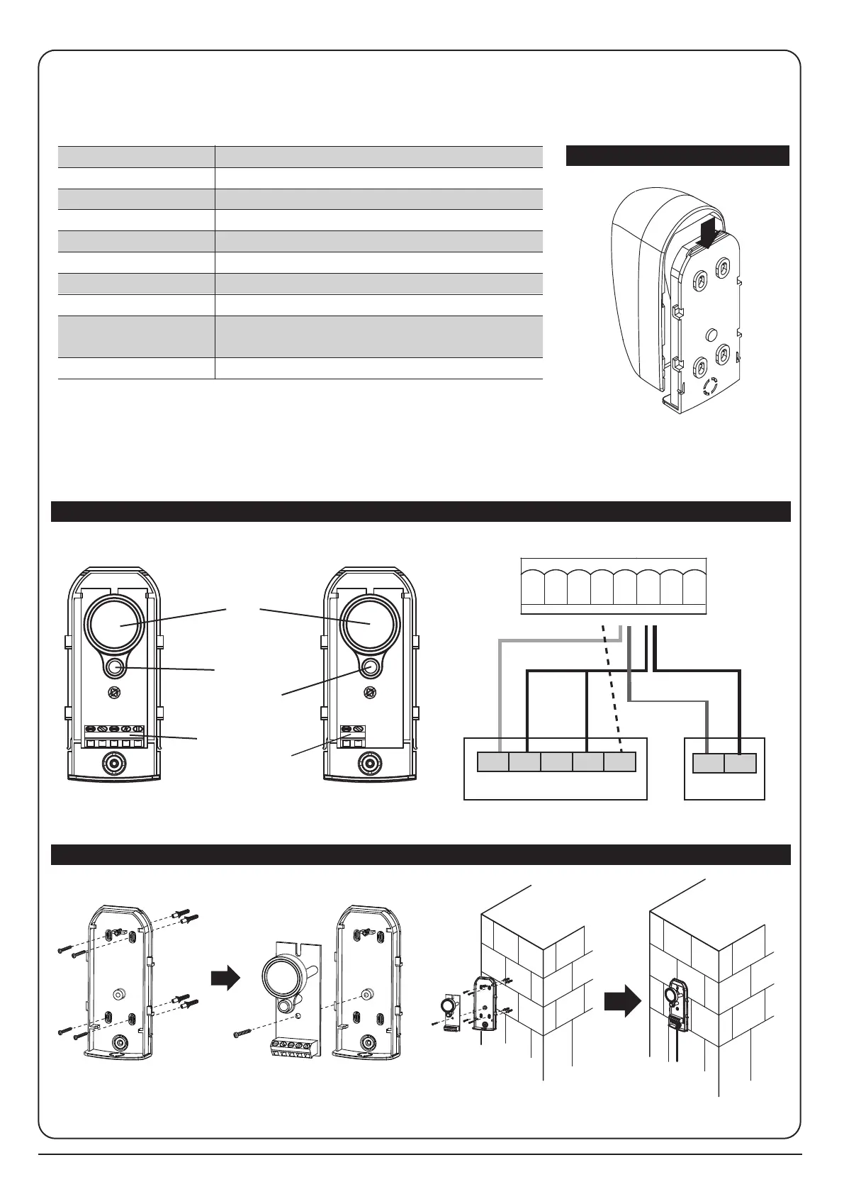
4. Photocell Installation
RX
Lens
Beam
Alignmnet
Indicator
Power LED
Indicator
Terminal Block
Power Terminal
Block
TX
The photocells are safety and security devices for gate openers and operators. They consist of one
transmitter and one receiver in waterproof covers; it is triggered by breaking the path of the beams.
Specifications:
1 2 3 4 5 1 2
Antenna
Lmt4Lmt3
Lmt2
ANT
GND
GND
GND
Lmt1
PC190-PCB1
40121-377-A1
SW1
RF-LEARN
RF1
J7
DOWN
NO
+
9 10 11 12 13 14 15 16 17 18
Installation: Wire Connection of Photocells
TX: Connect DC+ (1) to PhVcc and GND (2) to GND on the P190 motherboard.
RX: Connect DC+ (1) to PhVcc and COM (5) to Ph1 on motherboard. Connect
the GND (2) to the GND (24) on the motherboard.
Finally, connect a bridge between N.C (4) and GND (2) to the RX.
DC+ GND
TX
N.O. N.C. COM
RX
DKey
SKey GND Ph1 PhVcc GND Ph2 PhVcc
19 20 21 22 23 24 25 26
DC+ GND