17
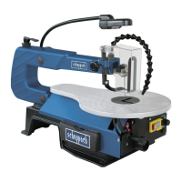
Blade guard assembly, Fig. 4
Install the blade guard to the holder as shown in the dia-
gram. Secure the screws with a nut and washer.
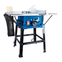
• Liftthesawontotheframeandbaseandpushitonto
the workbench.
• Familiarize yourself with the saw operating elements
and features.
Mounting the saw on a work bench, Fig. 5
• Aworkbenchmadefromsolidwoodisbetierthanone
made of plywood, as interfering vibrations and noise are
more noticeable with plywood.
• The necessary tools and small parts for assembling
the saw on a workbench are not supplied with the saw.
However, use equipment of at least the following size:
1 Saw body
2 Foam rubber base
3 Work bench
4 Flat seal
5 Washer
6 Hexagonal nut
7 Lock nut
8 Hexagonal bolt
Ouantity Description
4Hexagonalbolts(6mm)1/420xlength
4Flatseal(7mm)9/321.0
4Washers(7mm)9/321.0.
8Hexagonalnuts(6mm)1/420
First of all, drill holes into the seating surface and then
insert the screws.
• Afoamrubberbaseforreductionofnoiseisnotsup-
plied with the saw either. However, we expressly recom-
mend that you use such a base to keep vibration and
noise to a minimum. Ideal size 410 x 210 mm.
Montage du protecteur de lame, Fig. 4
Avec prudence, montez le protecteur de lame sur la scie,
comme I‘indique I‘illustration. Fixez súrement la vis avec
un écrou et une rondelle.
• SoulevezlascieparlecadreetlesocleetpoussezIa
sur la table d‘ouvrage.
• Familiarisezvousaveclesèlèmentsd‘utilisationetles
caractèristiques de puissance de la scie.
Montage de la scie sur un établi, Fig. 5
• UnétablienboismassifestplusadaptéàI‘installation
deJasciequ‘untréteauàpanneaudur,oúlavibration
et le bruit sont dérangeants.
• Lesoutilsetlepetitmatérieldemontagenécessaires
pour le montage sur un établi ne sont pas livrés avec la
scie.Utilisezcependantunéquipementquiaaumoins
la taille suivante :
1 Corps de la scie
2 Support en caoutchouc mousse
3 Table d‘ouvrage
4 Garniture plate
5Rondelle
6 Ecrou à six aretes
7 Contre-écrou
8 Vis à six arêtes
Quantité Description
4Visàsixaretes(6mm)1/420xlongueur
4Rondelles(7mm)9/32I.D.
8Ecrousà6aretes(6mm)1/420
5/16“(8mm)Dia.
4Rondelle(7mm)9/32I.D.
Commencez par percer les traus dans la surface partante
et mettez ensuite les vis.
• IIn‘estpasnonpluslivréaveclasciedesupporten
caoutchouc mousse. Mais nous recommandons forte-
ment I‘utilisation d‘un tel support pour maintenir un
faible niveau de vibration et de bruit. Taille ideale 410
x 210 mm.