english 21
Fig."A"
Fig."B"
Fig."F"
Fig."G"
Mounting
All assembly and retrofitting work may only be performed when the
mains plug has been disconnected.
Your scheppach circular sawbench is not completely assembled for
packaging reasons.
Assembly tools
Thefollowingareincludedinthescopeofdelivery:
1openendspanner 19mmwidthacrossats
1openendspanner 30mmwidthacrossats
1allenkey 5mmwidthacrossats
1allenkey 6mmwidthacrossats
1allenkey 4mmwidthacrossats
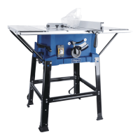
Parallel fence Fig. "A"
Screwthefencesection,inbetweenplateandguidingslide
together.Forthispurpose,insertthethreadedboltsinthe
guiding slide.
4 intermediate bushes
4 cheese head screws M 6 x 40
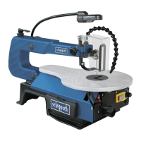
Fig. "B"
Attachtheintermediateplatetothefencesection.
- Do not tighten -
2 cheese head screws M 6 x 75
2 washers 6
2 wing nuts M 6
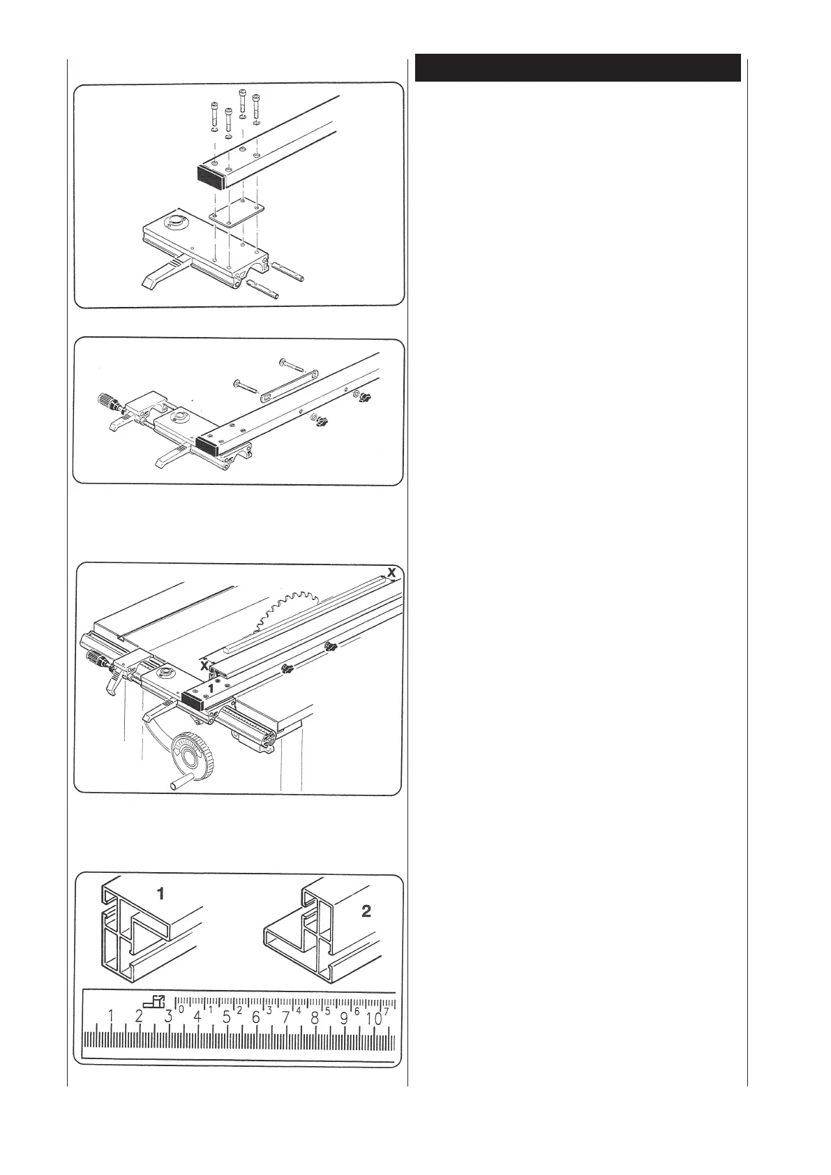
Parallel fence adjustment
Fig. "F"
•Opentheextenderleverontheslidingtable(pullupwarts)
and put it condescendingly on the guide tube
For precise adjustment of the parallel fence in relation to the
circularsawblade,releasethefourcheeseheadscrews(1),
andclamptheguideslideatadistanceofapprox.100 mm
fromtheblade.Placeastraightslatofapprox.600 mm length
againsttheblade.Alignthefenceparallelwiththesawblade
by repeated measurement (X) andreadjustment.Retightenthe
cheese head screws (1)
Important!
For cutting widths below 120 mm always use a push stick.
Stop rail
Fig. "G"
Position 1:
For working with raised stop bar surface. The displayed cut
width is on the black display scale.
Position 2;
For working with lowered stop bar sur- face.
Thedisplayedcutwidthisonthebluedisplayscale.(Lower
stopbarsurfacesymbol)