CDR Wireless Installation B1051302 Rev. B
23
6.2.2. Remote Mounting Options
The Antenna / Receiver and USB Interface can be wall-mounted as one unit (docked) or
separately (undocked) to achieve the best performance. When the two modules are
positioned separately, you will need to add the protective covers provided with your
system for the Antenna / Receiver and USB Interface. These covers will attach to the
connector panels of each module.
1. Using a Phillips screwdriver, remove the two screws that secure the Antenna /
Receiver and USB Interface during shipment. (See Figure 7.)
2. Using a Phillips screwdriver, secure the protective cover to the USB Interface with
one (#6 x 3/4) screw (provided). (See Figure 8.)
3. Using a Phillips screwdriver, secure the protective cover to the Antenna / Receiver
with two (#6 x 3/4) screws (provided). (See Figure 9.)
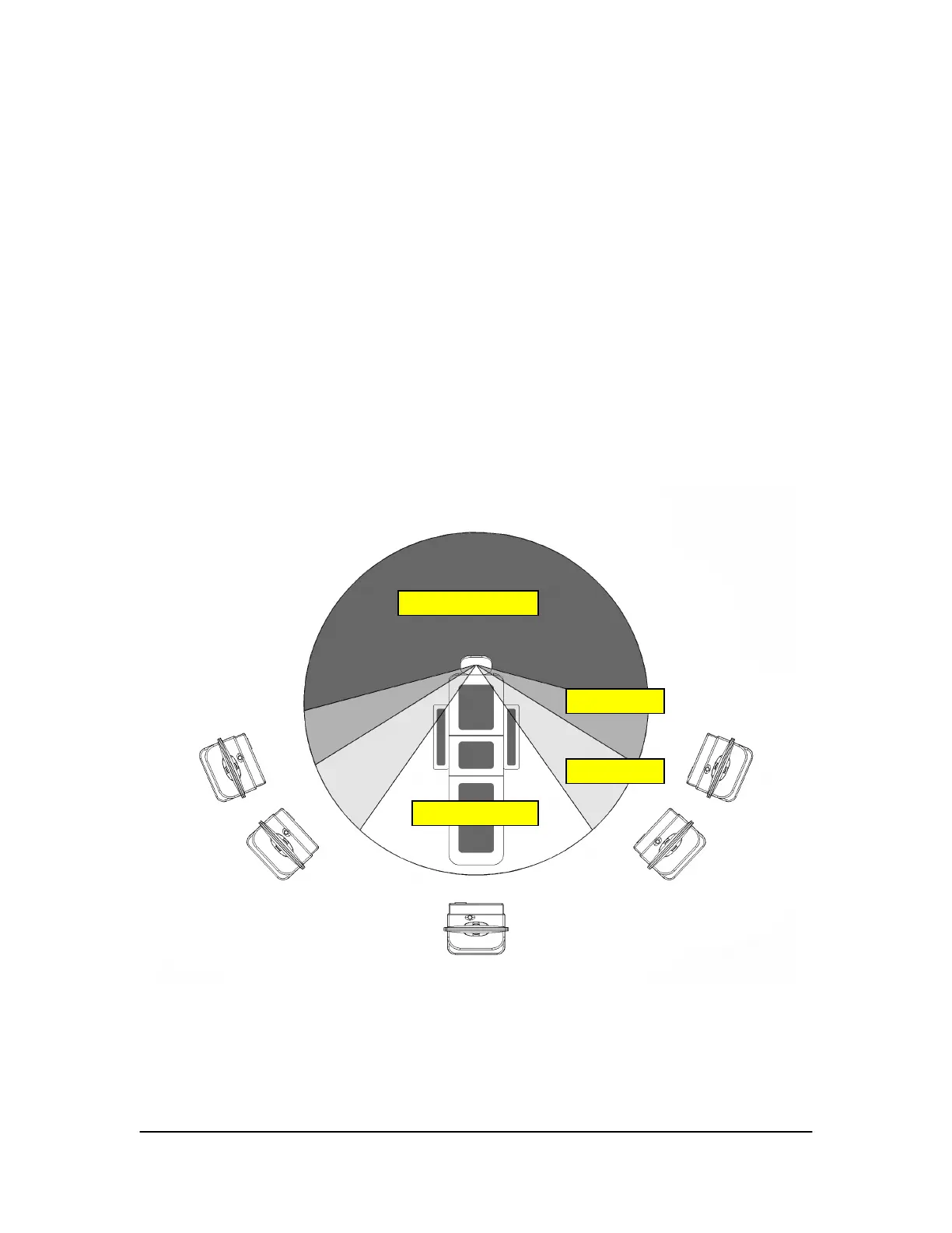
Figure 6. Antenna / Receiver Positioning Guidelines
(Distance between Sensor and Antenna / Receiver should be 6 feet (1.8 meters) or less)
Not Recommended
Mar
inal
cce
table
Recommended